|
|
Post by mastertech on Mar 21, 2019 15:04:12 GMT -5
Yeah they do look dirty. They also may have lost some spring tension. I have come across this many times even on socketed ic's. I usually take a screwdriver or stiff wire to get behind the metal part that touched the board and bend them out so they make stronger contact with the board strip. And I mean I really bend them out as far as i can. So I have to push harder to get the board back in. Have fixed many a problems doing this.
|
|
nashou
Unmoderated Off Topic
Tech in Training.....
Posts: 1,239 
|
Post by nashou on Mar 21, 2019 15:06:43 GMT -5
Yeah they do look dirty. They also may have lost some spring tension. I have come across this many times even on socketed ic's. I usually take a screwdriver or stiff wire to get behind the metal part that touched the board and bend them out so they make stronger contact with the board strip. And I mean I really bend them out as far as i can. So I have to push harder to get the board back in. Have fixed many a problems doing this. Yep, on it  |
|
|
|
Post by mastertech on Mar 21, 2019 15:08:30 GMT -5
I never had much luck with alcohol either. It was either lacquer thinner or sandpaper.
|
|
nashou
Unmoderated Off Topic
Tech in Training.....
Posts: 1,239 
|
Post by nashou on Mar 21, 2019 15:17:21 GMT -5
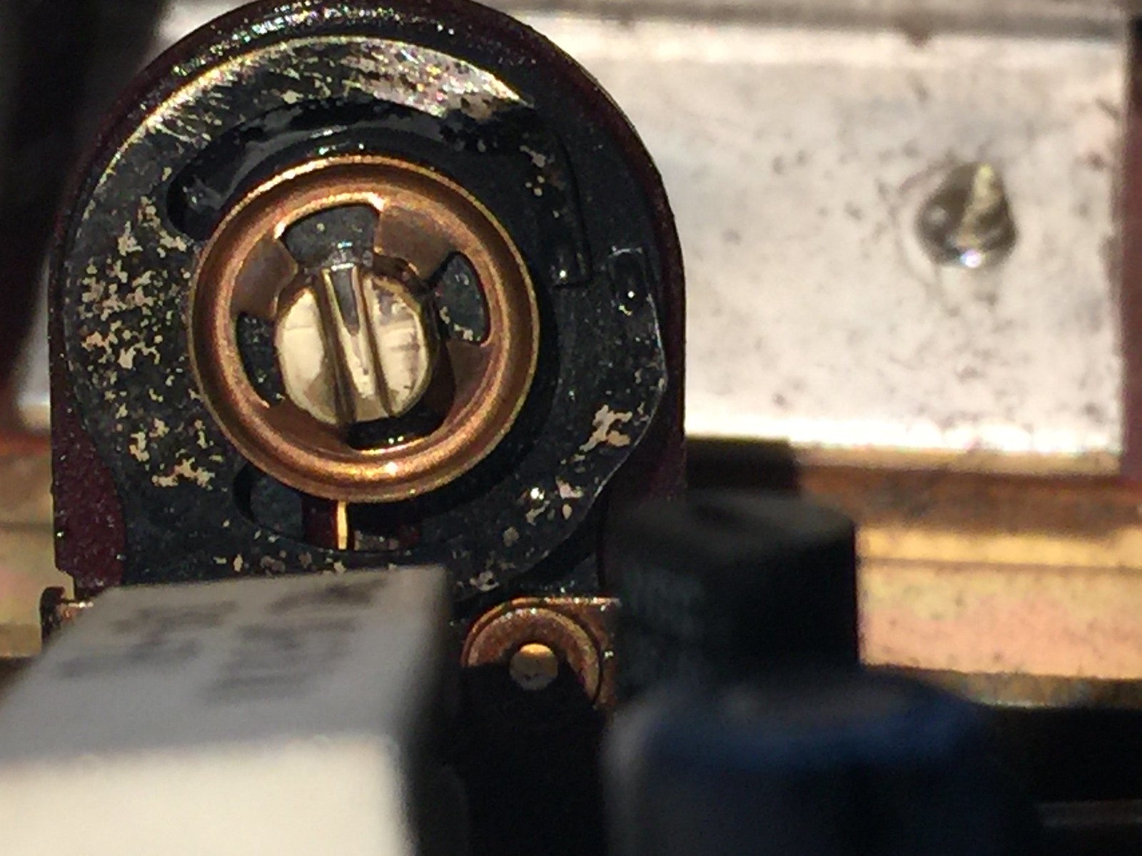
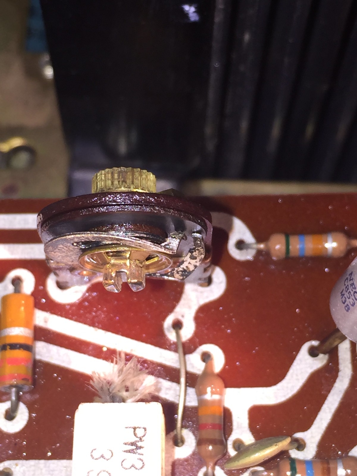
Look at these trim pots too Mac , Are the surface the two wiper blades come in contact suppose to be black or are they copper? Adjusting them made voltage change so I assumed they were fairly clean. What do you think?  |
|
nashou
Unmoderated Off Topic
Tech in Training.....
Posts: 1,239 
|
Post by nashou on Mar 21, 2019 15:25:52 GMT -5
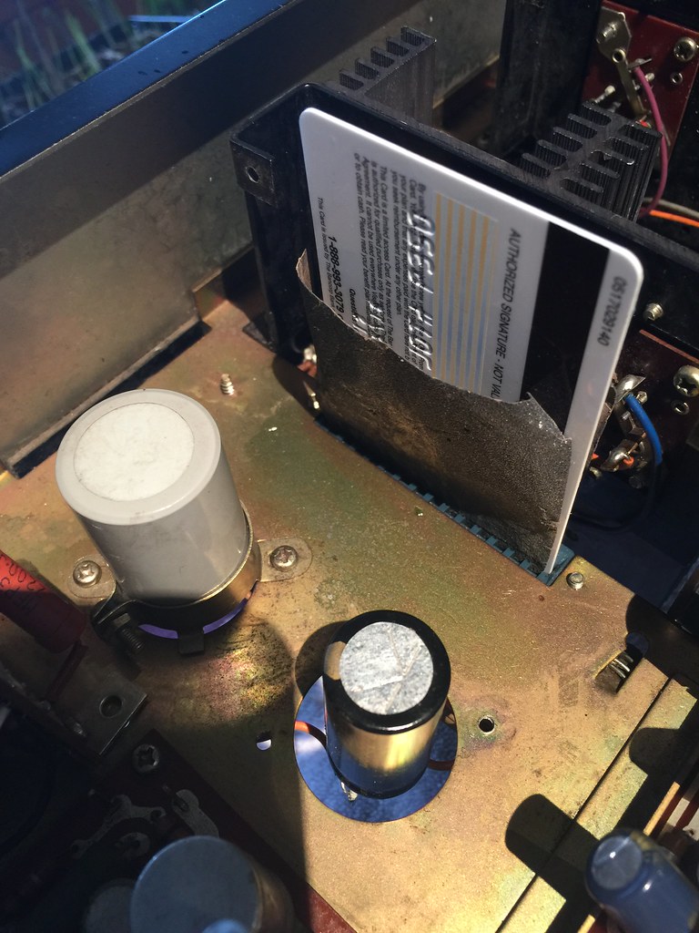
I never had much luck with alcohol either. It was either lacquer thinner or sandpaper. yes, this is how I did it . But the blades or fins fan out toward the bottom. No way to get in there and bend them out. So I hope the sand paper credit card swipe a few times with Radio shack cleaner lubricant will get them up to snuff.  |
|
|
|
Post by mastertech on Mar 21, 2019 15:32:07 GMT -5
What about a dental pick to bend them out? I use one often.
Those pots look terrible and I would not doubt that may be causing your drifting.
|
|
nashou
Unmoderated Off Topic
Tech in Training.....
Posts: 1,239 
|
Post by nashou on Mar 21, 2019 15:41:45 GMT -5
What about a dental pick to bend them out? I use one often. Those pots look terrible and I would not doubt that may be causing your drifting. I took some 180 grit sand paper and slid it under the two split wipers . then I tried to sand the surface the wipers contact but I think it is suppose to be black, like that carbon conductive material? Just the upper part not where the wipers are, not sure if id remove any conductive material , so I know in that area I never get the wipers to.  |
|
nashou
Unmoderated Off Topic
Tech in Training.....
Posts: 1,239 
|
Post by nashou on Mar 21, 2019 16:21:10 GMT -5
Ok, this amp is a strange one for sure.
Hooking up the head phones got me thinking. Why did the DC drop as soon as I connected a load to the amp?
And would the same thing happen if I connect speakers ?
So I decided to hook up speakers and measure DC on that same speaker output and then on the
speaker out with no speaker or load connected.
Guess what? No DC on out put while speaker connected, and the side with no load on it had DC !!!!
Have you ever heard of an amp like this? Or is there still something wrong?
It doesn't sound too bad either !
So what do you think ?
Athanasios
|
|
|
|
Post by mastertech on Mar 21, 2019 16:43:30 GMT -5
From the various similar circuits I have looked at on the output line besides that cap there should be 1 or 2 more resistors and sometimes another cap to gnd. The speaker may be acting like a resistor on that line but that is still not good. There should be no dc without the speaker. The speaker will overheat and possibly burn open the coil.
The headphone jack having another resistor may be just enough to remove that remaining DC because what ever is suppose to be removing it is not working properly.
As far as those pots are concerned you may want to look into replacing them.
|
|
nashou
Unmoderated Off Topic
Tech in Training.....
Posts: 1,239 
|
Post by nashou on Mar 21, 2019 17:03:40 GMT -5
From the various similar circuits I have looked at on the output line besides that cap there should be 1 or 2 more resistors and sometimes another cap to gnd. The speaker may be acting like a resistor on that line but that is still not good. There should be no dc without the speaker. The speaker will overheat and possibly burn open the coil. The headphone jack having another resistor may be just enough to remove that remaining DC because what ever is suppose to be removing it is not working properly. As far as those pots are concerned you may want to look into replacing them. I was thinking of adding another resistor to GND right at the speaker terminals on the inside . Would it be wise to go from the positive to negative speaker terminal with a resistor across it? How do I measure the value of those trim pots? And I'm going to recap the other board just so they match . let me know how I should proceed with the resistors, what value , wattage etc. I think I have some 2 water, but I think id need more watts correct? Or could I stack them if I only have 1 watters for testing? |
|
nashou
Unmoderated Off Topic
Tech in Training.....
Posts: 1,239 
|
Post by nashou on Mar 21, 2019 17:23:19 GMT -5
I think the pots are 1 to 3200 ohm pots. Measured from one pin to center pin and adjusted to see value change.
|
|
|
|
Post by mastertech on Mar 21, 2019 17:42:34 GMT -5
For the pots you just measure across the whole pot, not the trimmer. but you will probably have to remove it.
As far as resistors on those output lines here is what I would do. First do an ohm reading across the + and - of each speaker connector. This will tell you if there are any resistors on that side of the relay. Then do an ohm measurement from the neg side of each filter cap to gnd. That will tell you if there is any resistors on that side of the relay. let me know what you get.
|
|
|
|
Post by stridsvognen on Mar 21, 2019 17:51:32 GMT -5
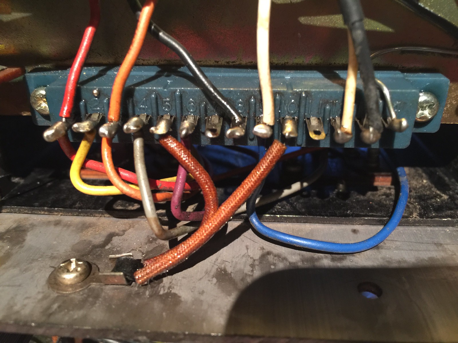
whats that on leg 11 on the right socket.?
|
|
nashou
Unmoderated Off Topic
Tech in Training.....
Posts: 1,239 
|
Post by nashou on Mar 21, 2019 18:05:21 GMT -5
For the pots you just measure across the whole pot, not the trimmer. but you will probably have to remove it. As far as resistors on those output lines here is what I would do. First do an ohm reading across the + and - of each speaker connector. This will tell you if there are any resistors on that side of the relay. Then do an ohm measurement from the neg side of each filter cap to gnd. That will tell you if there is any resistors on that side of the relay. let me know what you get. At speaker terminals no resistance OL , on neg filter cap pin to GND 220 ohm. Must be those resistors on the relay board. I looked I don't have any high watt resistors that are of a low value. I have some 560k and 10k 2 watters . Some smaller vales too from speaker cross overs like 7.5 ohms but 5 watts i have a lot of 1/2 watts. I could parallel them as a temp test ? Or could we use a cap as well? Nashou |
|
nashou
Unmoderated Off Topic
Tech in Training.....
Posts: 1,239 
|
Post by nashou on Mar 21, 2019 18:06:41 GMT -5
whats that on leg 11 on the right socket.? Nothing.  |
|