nashou
Unmoderated Off Topic
Tech in Training.....
Posts: 1,239 
|
Post by nashou on Mar 15, 2019 19:54:16 GMT -5
Hi I have this Mark III that I am going over for a friend. I had to re string the tuner . Clean it up etc. I have no Service manual so trying to set DC offset is a shot in the dark, not sure what to set it at if the trim pots are correct etc. The left amp that runs cool at about 86° but the right amp hit 236° !!!!At first the DC on the speaker outs were at 2.5 volts!!! I adjusted the trimpot on the amp board and got it to move but it was jumping all over the place got it into the mV's but ti go back up again and still ran hot. So I pulled the Output transistors Hirel 188's ? those tested fine in my parts tester. So i pulled the amp board out and tested all those transistors. those were fine. I decided to recap the board and try again, the two 47uf caps read 77uf so I was hoping it might be that. Nope, still runs hot. SO next i compared voltages at the pins of the good amp and the bad amp at the output transistor pins . They all seem close. +/- 23 VDC and .677 VDC . Forgot to mark the pins as source , drain gate etc. But they seem good. not sure what else to do . With out the schematics for voltage reference I'm kinda shotgunning it. Any one here ever work on one of have schematics for them? Or maybe know what this is based off of as I heard these might be similar to some pioneer models. I'll add some pics incase they look familiar to another model. 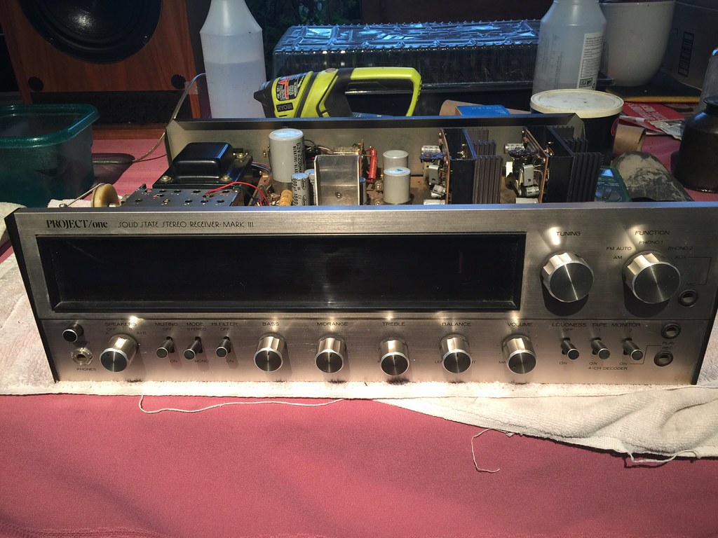  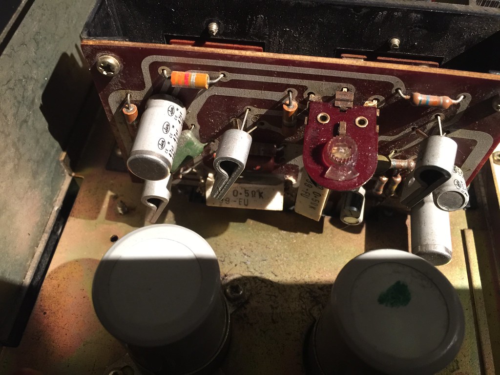 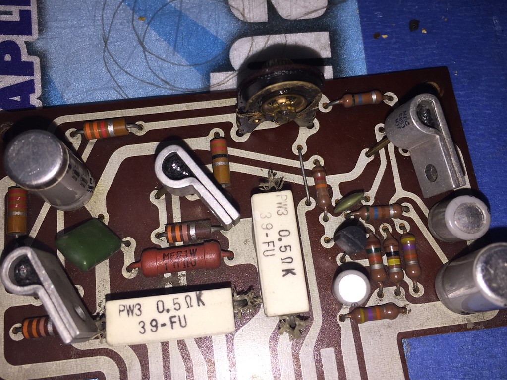 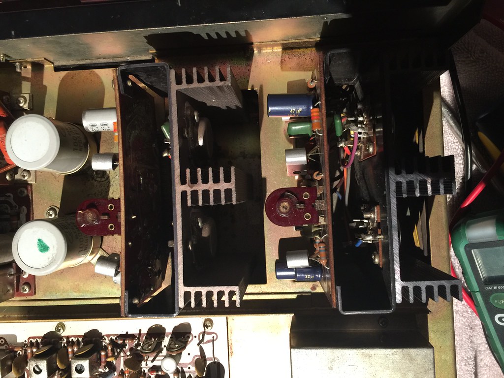 Re capped board 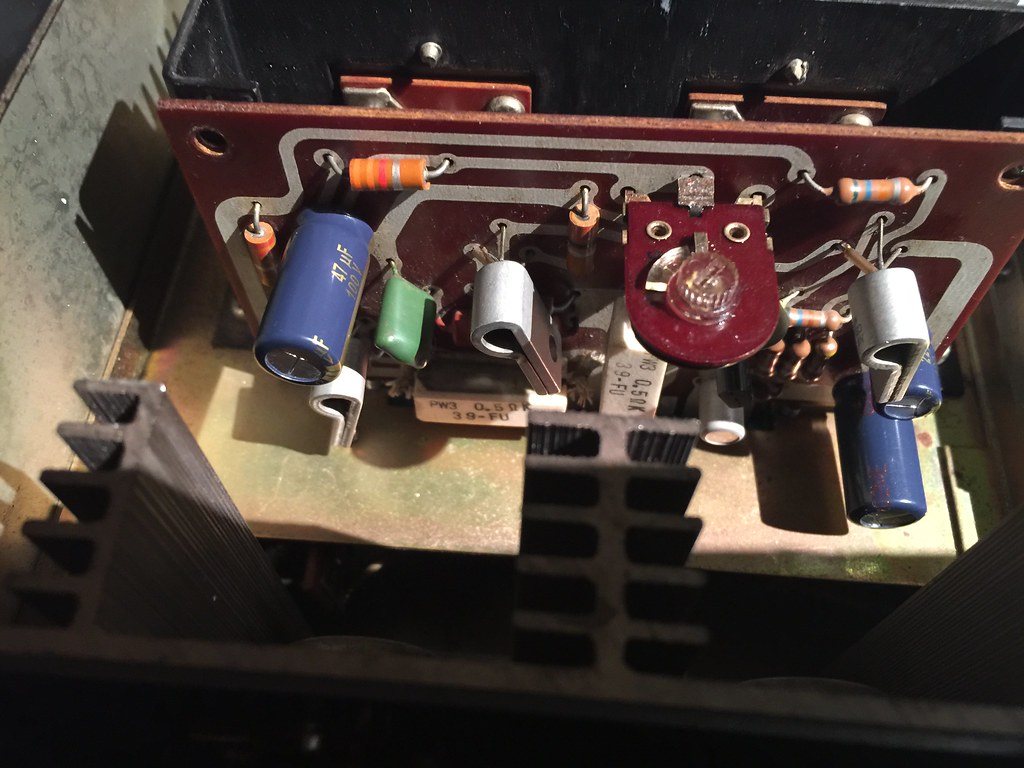 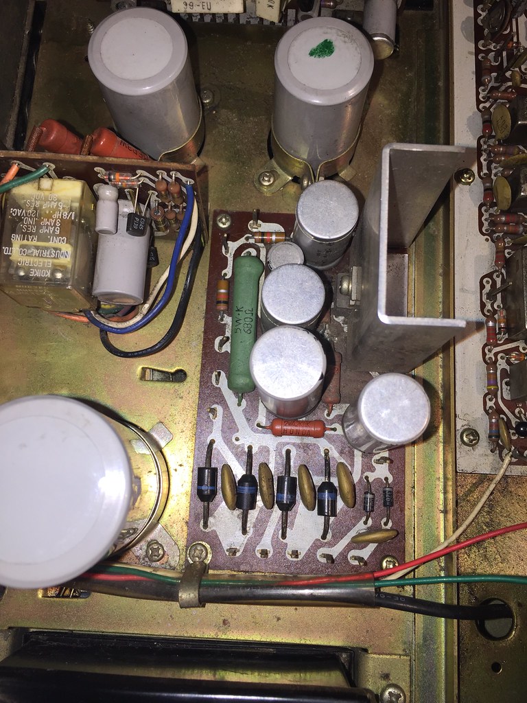 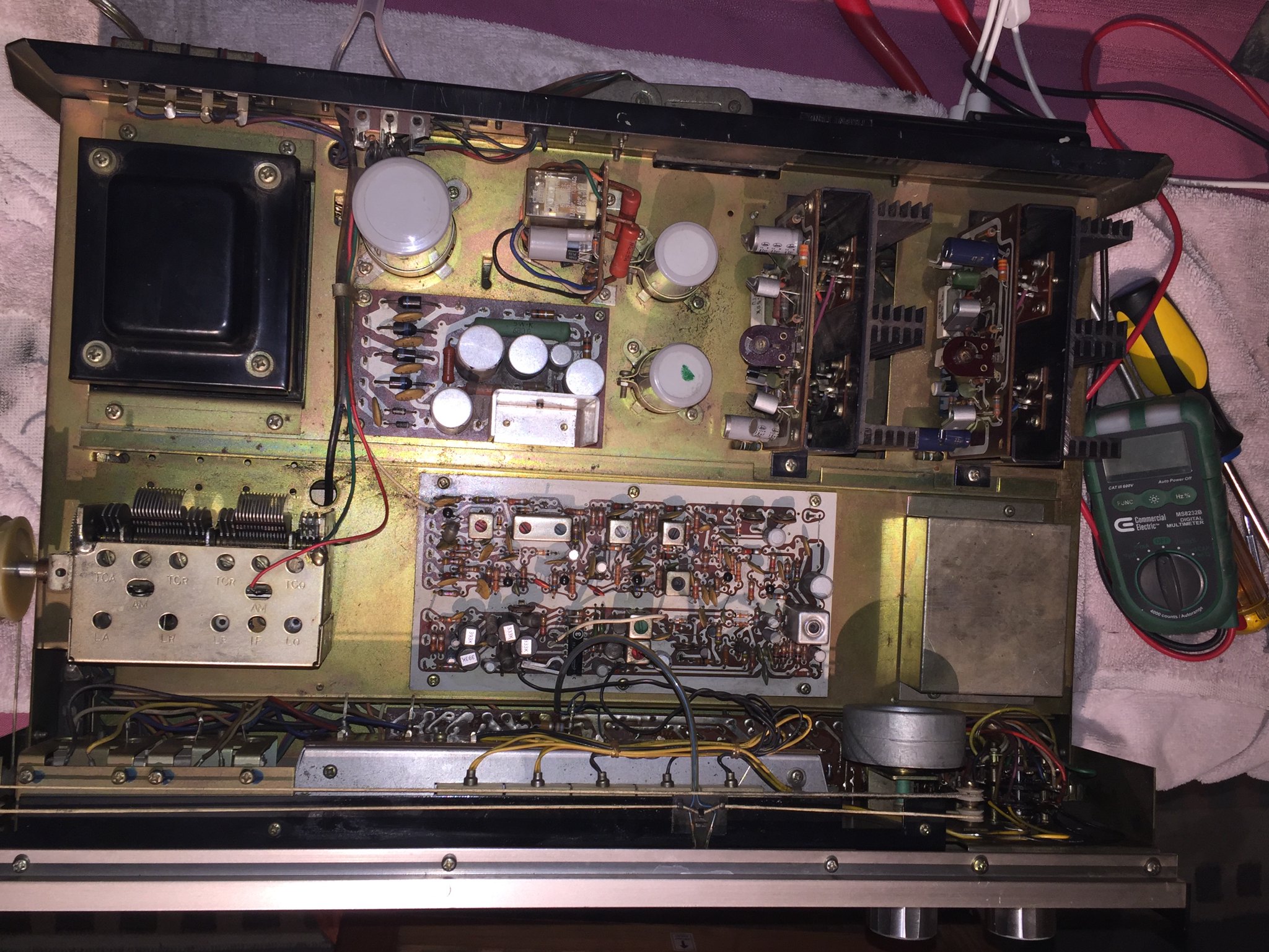 thanks guys. |
|
|
|
Post by stridsvognen on Mar 16, 2019 12:18:46 GMT -5
Whats bias over the emitter resistors?
|
|
nashou
Unmoderated Off Topic
Tech in Training.....
Posts: 1,239 
|
Post by nashou on Mar 16, 2019 17:06:06 GMT -5
Whats bias over the emitter resistors? I checked the DC at the speaker outputs first . both were bad but the one was over 3 volts . So I adjusted them down thinking that was why one was getting so hot. I was able to get then into mV range but the one was still hot. SO next i looked at the voltage on the trim pot pins , this was relatively the same as at the speaker outputs . But this time I noticed something odd. and verified it with measuring at speaker outs. I was able to get DC at speaker outs and at the trump pots down to .5mV's !! but then the amps would run extremely hot!!! If i raised the DC speaker outs they would be cool !! huh? Weird !!! And the left channel is way way to loud at barely any turning of the volume. I wonder now after typing this is there is a pre amp issue here? maybe its the culprit for the DC and heat. I think I measured this with the input set to tuner. Also this has pre amp ins and outs . I could re check DC at speaker out by removing the jumper correct? Athanasios |
|
|
|
Post by mastertech on Mar 16, 2019 18:20:05 GMT -5
Also this has pre amp ins and outs . I could re check DC at speaker out by removing the jumper correct? Athanasios Yes |
|
nashou
Unmoderated Off Topic
Tech in Training.....
Posts: 1,239 
|
Post by nashou on Mar 16, 2019 18:24:36 GMT -5
Also this has pre amp ins and outs . I could re check DC at speaker out by removing the jumper correct? Athanasios Yes Ok same results. Get DC into the low mV's and the amps get up to 200° get DC at outputs to 5 volts and amps run very cool, like 80° . And I set the input to AUX even tho the jumpers are removed. I.m using this trim pot, the only ones I see that are each on an amp board. I wish I had Schematics. I have read these Project/ones were the house brand for a store in Chicago called Playback.  |
|
nashou
Unmoderated Off Topic
Tech in Training.....
Posts: 1,239 
|
Post by nashou on Mar 16, 2019 18:26:41 GMT -5
I also measured at the white emitter resistor that is horizontal and got it 0.0 mv but the damn thing got super hot !!
Also was I right in thinking I can measure at the trim pot pins?
Nashou
|
|
|
|
Post by mastertech on Mar 16, 2019 18:29:08 GMT -5
I see that one pot adjustment is way different then the other one that looks like mid point. try switching those output transistors between channels and see if the same amp gets hot. You may have one transistor leaking and you are trying to overcompensate with the pot. if that does not change then try setting both pots to midpoint and get me the DC readings on both channels.
|
|
nashou
Unmoderated Off Topic
Tech in Training.....
Posts: 1,239 
|
Post by nashou on Mar 16, 2019 18:37:30 GMT -5
I see that one pot adjustment is way different then the other one that looks like mid point. try switching those output transistors between channels and see if the same amp gets hot. You may have one transistor leaking and you are trying to overcompensate with the pot. if that does not change then try setting both pots to midpoint and get me the DC readings on both channels. Mac I discovered both amps will get hot if I lower DC to the mV range . Whats weird is this amp seems to have a speaker protection relay . You turn it on and after a second the relay clicks in . So if any higher amount of DC was to be detected wouldn't the speaker relay not click and would I not be able to hear music? But I'll set both to mid point and measure the speaker outs on both channels. Athanasios |
|
|
|
Post by mastertech on Mar 16, 2019 18:45:12 GMT -5
I think that relay is for A/B speaker, but not 100% sure without schematic. Are all 4 of those outputs 188's?
|
|
nashou
Unmoderated Off Topic
Tech in Training.....
Posts: 1,239 
|
Post by nashou on Mar 16, 2019 18:52:00 GMT -5
I think that relay is for A/B speaker, but not 100% sure without schematic. Are all 4 of those outputs 188's? Yes all 4 are the same 188's On the right amp I got 2.6 VDC On the left amp i got 1.6 DC they were slowly going down as amp heated up, and I mean heated up!! Right amp was at 162 and left at 152 before i shut it down. 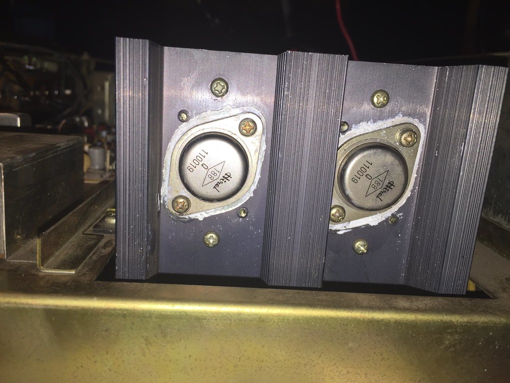 |
|
|
|
Post by mastertech on Mar 16, 2019 19:09:42 GMT -5
I am trying to find a circuit diagram that uses those 188's in parallel. No luck so far. Meanwhile I am curious what the rail voltages are going to that amp.. Can you check that?
|
|
nashou
Unmoderated Off Topic
Tech in Training.....
Posts: 1,239 
|
Post by nashou on Mar 16, 2019 19:12:44 GMT -5
I am trying to find a circuit diagram that uses those 188's in parallel. No luck so far. Meanwhile I am curious what the rail voltages are going to that amp.. Can you check that? I'll try to probe some areas on the amp and at the rectifier diodes . I'll probably find the rail voltages at the two resters at the top of the amp board correct? And in my first post I have voltages listed at the different pins on the 188's with black probe to chassis GND. Nashou |
|
|
|
Post by mastertech on Mar 16, 2019 19:24:07 GMT -5
Pull all those outputs and see if you still have DC on the speaker out lines.
|
|
nashou
Unmoderated Off Topic
Tech in Training.....
Posts: 1,239 
|
Post by nashou on Mar 16, 2019 19:30:01 GMT -5
I am trying to find a circuit diagram that uses those 188's in parallel. No luck so far. Meanwhile I am curious what the rail voltages are going to that amp.. Can you check that? ok on this pic if you look at the two resters on the top left one is vertical and the other is horizontal. On the vertical resistor at the top I get 51 vdc. On the horizontal resistor at the left side I get 41 VDC At the Power supply board I am getting 26 +/- , 51 , 39, and 14 at some of the points I measured. If you want more detailed info from that power supply board I'll mark up a pic if I can .  |
|
nashou
Unmoderated Off Topic
Tech in Training.....
Posts: 1,239 
|
Post by nashou on Mar 16, 2019 19:32:12 GMT -5
Pull all those outputs and see if you still have DC on the speaker out lines. ok will do, the right one will be easy the left one will be harder to get screw driver in there. Also not sure if anyone else worked on this but the right outputs had no thermal paste on them!!! But it looks factory installed, like they forgot at assembly |
|