nashou
Unmoderated Off Topic
Tech in Training.....
Posts: 1,239 
|
Post by nashou on Mar 16, 2019 21:19:39 GMT -5
You know, in thinking about this some more these may be Class A amps and 1 of those 188's on each channel may be a type of regulator. So we may just have to find out where that DC is coming from that is there now. I will look into this some more tomorrow. Darlington Amps also use the same transistors no? maybe its in that configuration? Ok Mac, I need to go to bed as well up at 5 am for work. Nashou |
|
|
|
Post by mastertech on Mar 16, 2019 21:20:24 GMT -5
2 NEC C853 M37 1 NEC A545 L34 And 1 NEC A640 M34 not on heat sink Did you test all 4 of these to make sure none are leaking? |
|
nashou
Unmoderated Off Topic
Tech in Training.....
Posts: 1,239 
|
Post by nashou on Mar 16, 2019 21:25:05 GMT -5
2 NEC C853 M37 1 NEC A545 L34 And 1 NEC A640 M34 not on heat sink Did you test all 4 of these to make sure none are leaking? tested them in my parts tester. They all tested fine. my tester gives what part it is, hFE and vfe |
|
|
|
Post by mastertech on Mar 16, 2019 21:27:00 GMT -5
If that is a class A amp then all that heat may be normal.  |
|
nashou
Unmoderated Off Topic
Tech in Training.....
Posts: 1,239 
|
Post by nashou on Mar 16, 2019 21:31:50 GMT -5
If that is a class A amp then all that heat may be normal.  236° was as hot as I let it go before I shut it down!!! lol And it didn't sound right. Also to get the dc into the millivolt range the trim pots were at one extreme , or at the end of adjustment range. Not sure what this is but lets see how far we can go and find out why there is the same DC voltage at the speaker outs even with out the output transistors in place. off to bed, thanks Mac and have a good nights sleep. nashou |
|
|
|
Post by stridsvognen on Mar 17, 2019 1:43:30 GMT -5
Are you sure the trimpots are not bias trimpots.?
The 0,0mv on the very hot emitter sound odd, what do it measure if you set Vdc?
I would guess the 4 white 0,5 ohm is the emitters, are the risistance ok on all of them, and do anything happen if you adjust the trimpots while measuring mVdc or Vdc over those.?
The heat thanges you get adjusting the trimmers sounds like your changing the bias setting, wich will also mess with the DC output.
|
|
nashou
Unmoderated Off Topic
Tech in Training.....
Posts: 1,239 
|
Post by nashou on Mar 17, 2019 5:33:55 GMT -5
Are you sure the trimpots are not bias trimpots.? The 0,0mv on the very hot emitter sound odd, what do it measure if you set Vdc? I would guess the 4 white 0,5 ohm is the emitters, are the risistance ok on all of them, and do anything happen if you adjust the trimpots while measuring mVdc or Vdc over those.? The heat thanges you get adjusting the trimmers sounds like your changing the bias setting, wich will also mess with the DC output. The resistors all measure .5ohms as they should. I can adjust the voltage to 0mV's Vdc while adjusting the trim pots. I'll double check again later today after i get home from work and see what adjusting the trimmers do across the emitter resistors. I just assumed they were the DC offset trimpot as they changed the dc on the speaker outs. you might be right with them being a bias setting. If so and I set for nominal heat on the transistors then we have a lot of dc on the speaker outs from somewhere else. Nashou |
|
|
|
Post by stridsvognen on Mar 17, 2019 14:01:02 GMT -5
Normaly that would indicate a transistor somewhere has gone crazy, it might test working, seen that quite a few times before, but ill guess most of those components are obsolete, so you could try just move 1 or 2 transistors to the other channel at a time untill you find the one that trows it off.
|
|
|
|
Post by mastertech on Mar 17, 2019 15:31:41 GMT -5
Let me know when you are ready to try some stuff. I have gathered some info that may be helpful.
|
|
nashou
Unmoderated Off Topic
Tech in Training.....
Posts: 1,239 
|
Post by nashou on Mar 17, 2019 15:50:55 GMT -5
Ok Some new information.
Kurt, Adjusting the trim pots does nothing across the emitters while the output transistors are
out of the amp.
Now not sure what happened when the output transistors are installed. not ready top test that yet because i have
something else going on.
Mac, I decided to remove the amps driver boards and power up to test some voltages with out the boards installed.
And also went to check for DC on the speaker outputs. DING DING DING DING!!!! I have 17 vdc( fluctuates up and down a volt or two) on the left channel.
That is the one that seemed way too loud for the barely above minimum volume control. the right speaker out is ok with a 1 mV reading.
So where do I look?
My Guess is the relay board .
let me probe voltages there
nashou
Nashou
|
|
nashou
Unmoderated Off Topic
Tech in Training.....
Posts: 1,239 
|
Post by nashou on Mar 17, 2019 15:51:22 GMT -5
Let me know when you are ready to try some stuff. I have gathered some info that may be helpful. Read post above . |
|
nashou
Unmoderated Off Topic
Tech in Training.....
Posts: 1,239 
|
Post by nashou on Mar 17, 2019 16:01:17 GMT -5
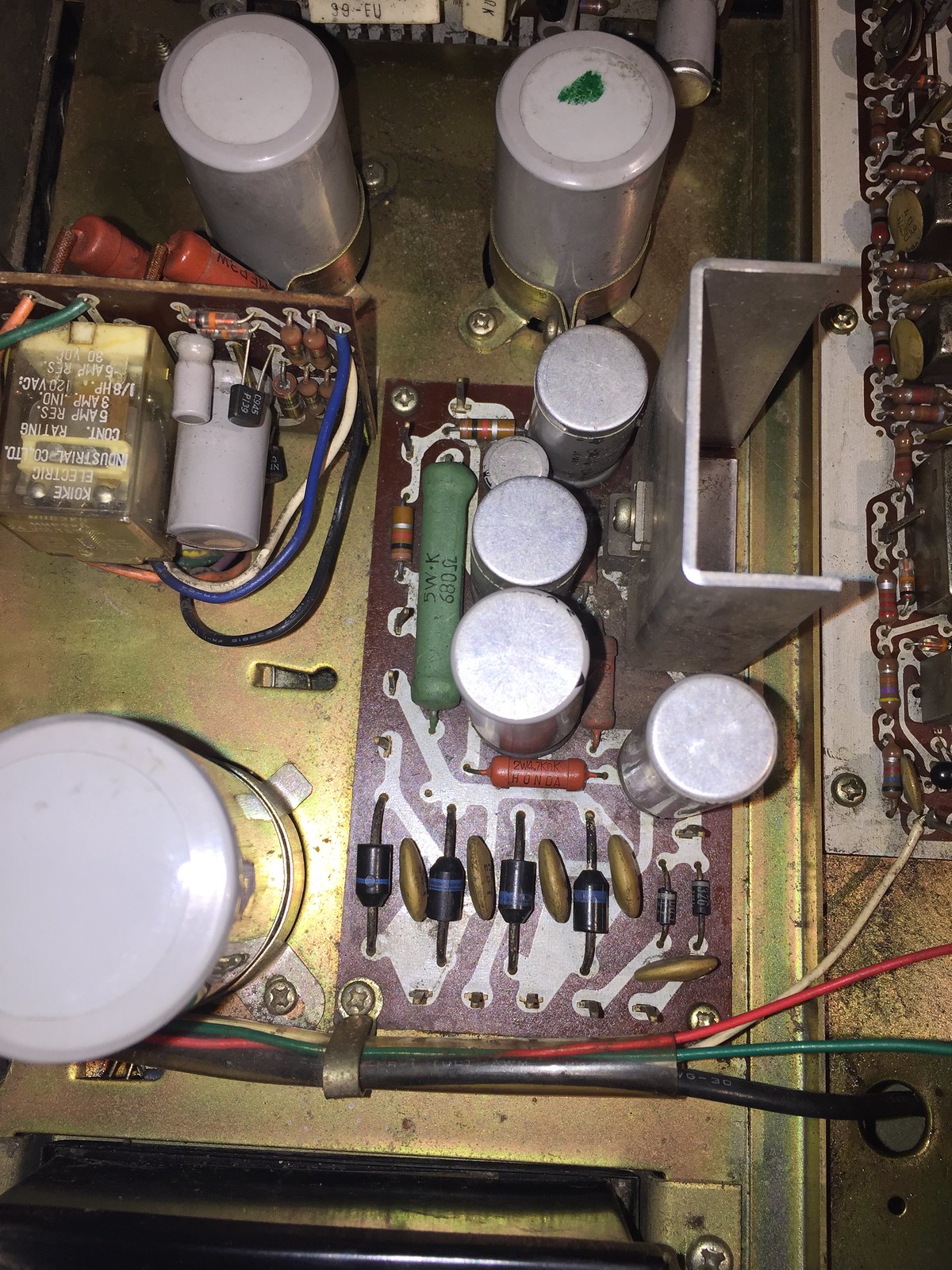
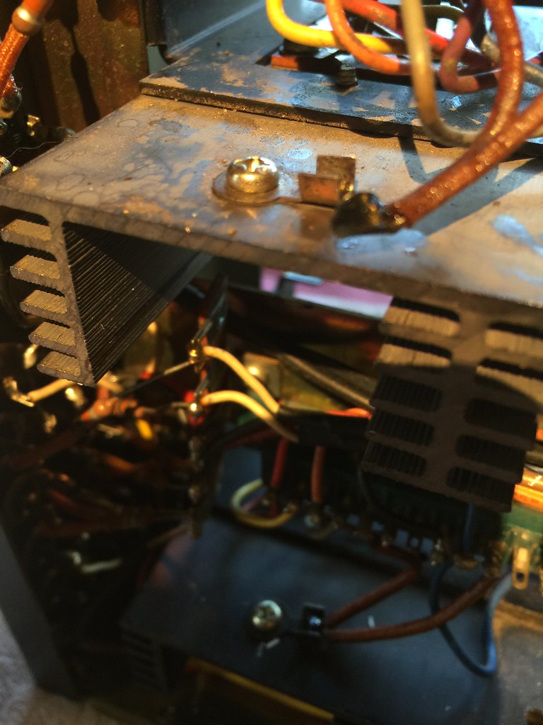
One more thing, might be normal but I don't think so. The Large aluminum heat sink for a transistor has voltage on it, 27.72 volts DC?  Whats up with that? Edit: And found these two wires tied together that look like they might be a thermal protection sensor? You can see the one on the bottom heat sink in place. looks like epoxy coated?  Nashou |
|
|
|
Post by mastertech on Mar 17, 2019 16:40:45 GMT -5
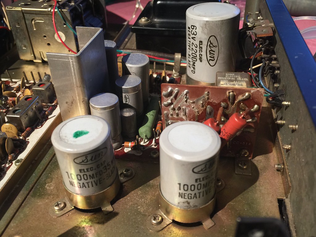
Well as I was doing some gathering today i started to remember working on some of these Class A amps many, many, many years ago, lol. So I pulled some schematics from some old stereo receivers and a found a couple with similar amps to yours. I noted all the same outputs, 1 output with higher voltages like yours and 1 output with lower voltages like yours. I will attach a schematic for a reference. Now on this schematic the manual describes how to set idle current which we can discuss later. But another thing of note is this type of amp appears to suppose to have a DC voltage on the output line, in this schematic 29v. There is a filter cap later in the system to remove that DC which here is a 2200uf/63v. I see 2 large can caps in your pics in the middle of the unit. What is the value on these. I think if we reference this schematic and try to put things together we can figure this out. So I would first suggest we see if we can determine if an amp output line goes to a cap and then the protect relay and then speaker terminal or in a similar order of relay and then cap. Can you check for this?  |
|
nashou
Unmoderated Off Topic
Tech in Training.....
Posts: 1,239 
|
Post by nashou on Mar 17, 2019 18:13:48 GMT -5
ok let me look, in your schematic, which two transistors would be similar to mine H001 and H002?
|
|
nashou
Unmoderated Off Topic
Tech in Training.....
Posts: 1,239 
|
Post by nashou on Mar 17, 2019 18:22:05 GMT -5
ok here is a pic, I have two 1000uf 35 volts and one 2200 uf 63 volt.  |
|