|
|
Post by mastertech on Mar 17, 2019 18:33:23 GMT -5
ok let me look, in your schematic, which two transistors would be similar to mine H001 and H002? Yes, H001 an H002 would be your 188's. |
|
nashou
Unmoderated Off Topic
Tech in Training.....
Posts: 1,239 
|
Post by nashou on Mar 17, 2019 18:58:35 GMT -5
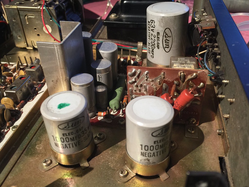
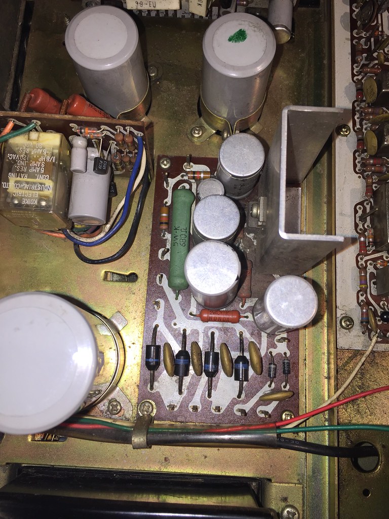
ok let me look, in your schematic, which two transistors would be similar to mine H001 and H002? Yes, H001 an H002 would be your 188's. Ok i followed the left output speaker wire which was blue, it went to speaker selector switch then went to yellow , verified using continuity on DMM. From there it goes to a terminal bus. From that bus it goes to the relay then I got stuck till i realized I need to power it up to make continuity. The yellow goes into the relay and continuity then transfers to a purple wire which goes to one of those 1000uf caps on the black pin ( negative side ) then the positive side of that said cap turn to an orange wire and that goes to the connector for the driver board which has another orange wire going to one pin of the output transistor. So you are right!!! this is a class A amp design !!! I take it my next step is to check that cap? can I do it in circuit? Athanasios |
|
nashou
Unmoderated Off Topic
Tech in Training.....
Posts: 1,239 
|
Post by nashou on Mar 17, 2019 19:04:35 GMT -5
Only thing is I don't see in your schematic the 2200uf 63 volt cap? Just want to see the path for my own knowledge growth  Nashou |
|
|
|
Post by mastertech on Mar 17, 2019 19:37:01 GMT -5
Great. Rather then testing those caps I think what should be done next is put everything back together and get it running again since we have a better understanding of what we are working with. Then we do the idle current adjustment and see if it comes with in spec and if we have the 29v on both amp outputs. Then if we have that and there is still some DC getting by those caps we then address them. I will attach some more schematics for your pleasure, lol. I marked a few things to help you follow.  |
|
nashou
Unmoderated Off Topic
Tech in Training.....
Posts: 1,239 
|
Post by nashou on Mar 17, 2019 19:40:36 GMT -5
Awesome!!!!
So Kurt was also right!1 Thanks guys.
Give me some time to put it back. Needs new thermal past on the left amp. The freaking right one never had any
on them!!!
Athanasios
|
|
|
|
Post by mastertech on Mar 17, 2019 19:45:32 GMT -5
Oh, that reminds me of your post saying you had DC on those heatsinks. Was that with those outputs all removed and was it the same on both heatsinks?
Also, remind me later to elaborate on that thermal device and the wires soldered together. I believe i have your answer for that also but don't want to get into that right now.
|
|
nashou
Unmoderated Off Topic
Tech in Training.....
Posts: 1,239 
|
Post by nashou on Mar 17, 2019 20:05:05 GMT -5
Oh, that reminds me of your post saying you had DC on those heatsinks. Was that with those outputs all removed and was it the same on both heatsinks? Also, remind me later to elaborate on that thermal device and the wires soldered together. I believe i have your answer for that also but don't want to get into that right now. ok back together and awaiting your instructions. I might use a power monitoring plug that uses bluetooth and I can monitor power consumption via a phone app. Its a Revogi plug might be helpful during bias settings. Not the amps heat sinks the one on the power supply picture here   Ok all set and ready to start testing. Nashou |
|
|
|
Post by mastertech on Mar 17, 2019 20:27:34 GMT -5
Ok, since this schematic is different then yours this is in experimental stage. We have to see if that pot on you amp does affect where we are testing at. So according to this schematic you would connect you DC volt meter across R774. So when you look at the schematic you have to find that resistor by location on your amp board. Then turn on unit and see if that pot affects your voltage reading. If it does then see if you can set it at around 5mv. IF that all goes well then test the DC on the amp output line and see if you have around 29v.
|
|
nashou
Unmoderated Off Topic
Tech in Training.....
Posts: 1,239 
|
Post by nashou on Mar 17, 2019 20:32:16 GMT -5
ok, i'll look for it and test.
|
|
nashou
Unmoderated Off Topic
Tech in Training.....
Posts: 1,239 
|
Post by nashou on Mar 17, 2019 20:36:32 GMT -5
wait do you mean 774? I cant find 744 on your schematic?
If it is 774 then I think those are the Emitter resistors correct?
Nashou
|
|
|
|
Post by mastertech on Mar 17, 2019 20:37:37 GMT -5
Ooops, Yes R774. I will correct above.
|
|
|
|
Post by mastertech on Mar 17, 2019 20:40:26 GMT -5
If it is 774 then I think those are the Emitter resistors correct? Nashou Actually in this amp design that is an emitter resistor. The adjoining one is a collector resistor. |
|
nashou
Unmoderated Off Topic
Tech in Training.....
Posts: 1,239 
|
Post by nashou on Mar 17, 2019 20:43:42 GMT -5
If it is 774 then I think those are the Emitter resistors correct? Nashou Actually in this amp design that is a collector resistor. The adjoining one is an emitter resistor. Hard to tell which is with so I measure across the one that horizontal and was able to lower voltage .5mV but I decided to put the other amps trim pot in the same relative area and the voltage changed on the other amps resistor? So one affects the other or am i measuring the wrong resistor? Should I measure the voltage across the other resistor on the same amp? oh let me get the voltage off that transistor . nashou |
|
|
|
Post by mastertech on Mar 17, 2019 20:48:33 GMT -5
Actually we are looking for 5mv, not .5mv
|
|
nashou
Unmoderated Off Topic
Tech in Training.....
Posts: 1,239 
|
Post by nashou on Mar 17, 2019 20:48:36 GMT -5
Ok i think its the right resistor, as its on the same side as the transistor that has 29.33 volts DC on one pin, the top pin, if thats the output. the other transistor has only .xx mV
speaker out put was at 3.0 vdc
Athanasios
|
|