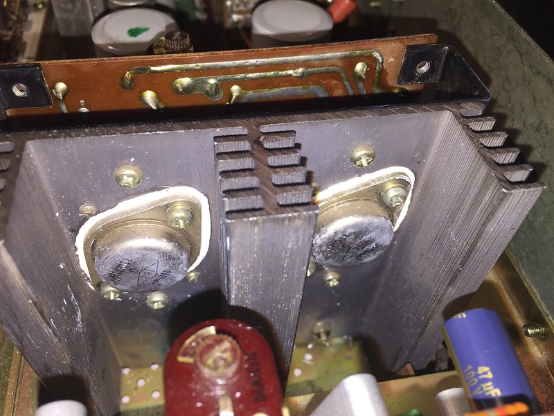
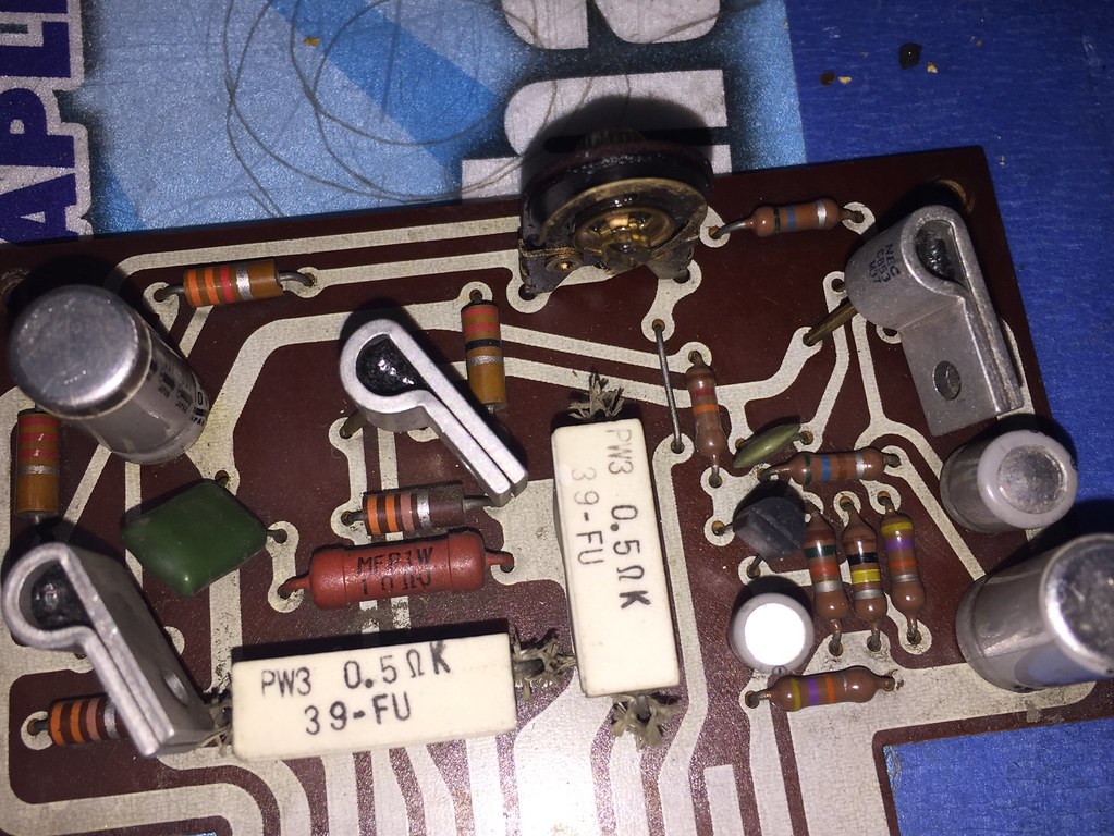
nashou
Unmoderated Off Topic
Tech in Training.....
Posts: 1,239 
|
Post by nashou on Mar 17, 2019 20:48:59 GMT -5
Actually we are looking for 5mv, not .5mv ok I'll re adjust . |
|
|
|
Post by mastertech on Mar 17, 2019 20:51:23 GMT -5
What is the voltage on the amp output, not speaker.
|
|
nashou
Unmoderated Off Topic
Tech in Training.....
Posts: 1,239 
|
Post by nashou on Mar 17, 2019 20:55:34 GMT -5
What is the voltage on the amp output, not speaker. 29.33 VDC Across the resistor it was negative .5 maybe cause the probes were reversed? Nashou |
|
nashou
Unmoderated Off Topic
Tech in Training.....
Posts: 1,239 
|
Post by nashou on Mar 17, 2019 21:02:06 GMT -5
|
|
|
|
Post by mastertech on Mar 17, 2019 21:06:30 GMT -5
Yes that is the data sheet. The line I am calling the output lines are the ones that go to the 2 can style filter caps, 1 line from each channel. You are using chassis for neg probe, correct? |
|
|
|
Post by mastertech on Mar 17, 2019 21:08:43 GMT -5
How about this. using chassis as gnd you should have around 29v on any leg of all 4 of those emitter resistors.
|
|
nashou
Unmoderated Off Topic
Tech in Training.....
Posts: 1,239 
|
Post by nashou on Mar 17, 2019 21:09:13 GMT -5
Yes that is the data sheet. The line I am calling the output lines are the ones that go to the 2 can style filter caps, 1 line from each channel. You are using chassis for neg probe, correct? yes chassis to neg probe. Ok I'll have to do it on the relay board as trying to get to orange wire will be hard as its on the bottom and put the cover on . Is that ok? But I might be able to get probe down to the bad connector where the output goes. |
|
|
|
Post by mastertech on Mar 17, 2019 21:13:23 GMT -5
Just do this. Put neg probe in either neg speaker connector then with pos probe test legs of white emitter resistors. Should be around the same on all.
|
|
nashou
Unmoderated Off Topic
Tech in Training.....
Posts: 1,239 
|
Post by nashou on Mar 17, 2019 21:15:11 GMT -5
How about this. using chassis as gnd you should have around 29v on any leg of all 4 of those emitter resistors. yes I have 29.3 and 29.74 on the right transistor . of the left amp . similar results on the right amp even with out adjusting it yet.  |
|
|
|
Post by mastertech on Mar 17, 2019 21:20:00 GMT -5
I would rather you check it like in my post just before your last. On those resistors
|
|
nashou
Unmoderated Off Topic
Tech in Training.....
Posts: 1,239 
|
Post by nashou on Mar 17, 2019 21:21:06 GMT -5
Just do this. Put neg probe in either neg speaker connector then with pos probe test legs of white emitter resistors. Should be around the same on all. ok on each amp I have just over 29 volts DC on the two white resters that are horizontal both ends. On the vertical ones I do not, well only measured at top cant get to the bottom leg of the vertical ones. those are .3 and .9 mV  Nashou |
|
|
|
Post by mastertech on Mar 17, 2019 21:28:06 GMT -5
Hmm, your amp must be different then the schematic one cause it should not be testing that way. At any rate you have 29v from each amp on the wire going to the big caps, right?
Are the amps heatsinks running cool? Or should I say not hot?
|
|
nashou
Unmoderated Off Topic
Tech in Training.....
Posts: 1,239 
|
Post by nashou on Mar 17, 2019 21:31:26 GMT -5
Hmm, your amp must be different then the schematic one cause it should not be testing that way. At any rate you have 29v from each amp on the wire going to the big caps, right? Are the amps heatsinks running cool? Or should I say not hot? Let me let it run for a bit, i keep shutting it down waiting for response. |
|
|
|
Post by mastertech on Mar 17, 2019 21:34:04 GMT -5
Recheck your DC on the speaker outs now while it is running.
Also be careful touching these heatsinks when this is on. They may be carrying unprotected voltage.
|
|
nashou
Unmoderated Off Topic
Tech in Training.....
Posts: 1,239 
|
Post by nashou on Mar 17, 2019 21:42:07 GMT -5
Recheck your DC on the speaker outs now while it is running. ok the one amp i adjusted to 5 mV, left, is running cooler than the right amp which I did not adjust. Remember adjusting the right amp altered the reading across the resistor . the left amp running cool at 80° has 3.1 vdc, the right amp running hot at 165° voltage is 4.5 vdc |
|