howie
Junior Member

Posts: 87 
|
Post by howie on Dec 20, 2015 20:34:20 GMT -5
Just laughing at this. Does anyone even remember why Curt started his own site? Well it was for just that reason.
To much moderation and censorship at AVS.
|
|
howie
Junior Member
Posts: 87
|
Post by howie on Dec 20, 2015 7:26:09 GMT -5
Well the standby led is usually turned on by the processor and a properly working eeprom is usually required for the processor to work so I cannot fully agree with that statement. But without a schematic I cannot really say where is what. I would go to the main processor and see if it is receiving power. You can find which pins should have power with a datasheet of that ic, if one is available. Also, see if you can trace back the standby led lines and see what they connect to ordered eeprom. Worst case I wasted $15.00. That is as far as I will go with it. |
|
howie
Junior Member
Posts: 87
|
Post by howie on Dec 16, 2015 5:42:18 GMT -5
The board repair is pretty cheap so it cannot be much of a repair. Could be the Eeprom replacement. The only thing you can check on the eeprom is for a short to gnd. Most likely that eeprom is preprogrammed. Most tv ones are. So buying one from a basic supplier is probably blank and would not work. I did get a reply back from the eeprom supplier and he suggests that if there's no stdby led that it's the power supply. It's a 19 VDC brick that works on another device. I have power all over the board but it's totally unresponsive. |
|
howie
Junior Member
Posts: 87
|
Post by howie on Dec 15, 2015 7:04:37 GMT -5
Is it safe to assume part of his fee includes programming and some markup?
|
|
howie
Junior Member
Posts: 87
|
Post by howie on Dec 15, 2015 5:41:31 GMT -5
Is there a way to test that part in the first link before I order it. He's asking $15.00 for a -$4.00 part but I can't seem to find it local. |
|
howie
Junior Member
Posts: 87
|
Post by howie on Dec 13, 2015 16:56:56 GMT -5
This is a LED flatscreen that uses a 19VDC brick for a power supply. I have not been successful in finding anything useful to help in the repair. I have followed power down to the small LED board and confirmed power to the board. There is a 4 wire connector on the board with red, orange, brown and black. Black and brown seem to be grounds and I'm showing 4.99 volts on the red and 4.89 volts on the orange. I would think the standby led should be lit. Help oh yee master of the electrical.........stuff.  |
|
howie
Junior Member
Posts: 87
|
Post by howie on Feb 8, 2015 8:56:43 GMT -5
Here we go again Same model of touch screen but not the same one. Crestron TPS 6000 table top version. Every once and a while the touch screen would not respond to touch and come back to life. Un plug it, wait a minute and plug it back in and it would reboot and be normal. This time no such luck. It is not completely dead as the cooling fan on the optional RGB board is spinning, I hear that the audio is getting power and the ethernet port led flicker. There are a bunch of tan 3-leg fuses under the cover that I have to test. Why 3 legs and how to test them 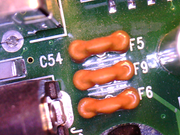 |
|
howie
Junior Member
Posts: 87
|
Post by howie on Jan 17, 2015 21:39:44 GMT -5
That did it. I scabbed a 150uf 400V cap off a AmPro horizontal bd I had kicking around and she's off and running.
|
|
howie
Junior Member
Posts: 87
|
Post by howie on Jan 17, 2015 19:04:52 GMT -5
Interesting tidbit The large 150uf 450V cap on the bd which has never been (as far as I know) been a issue with these won't even read on my Atlas ESR+ ER70
I couldn't get a in circuit reading off of it. It's glued to the bd so I snipped one leg to get a out of circuit reading from it. Stll would not read. The meter just says testing and then times out and shuts off.
|
|
howie
Junior Member
Posts: 87
|
Post by howie on Jan 17, 2015 18:47:03 GMT -5
Only found one bad cap. It was a 1000uf 25V cap at CM856 Replaced it with same value but a 35V. Replaced CM851 and CM852 because I had them. Actually pulled and tested the rest of them to be OK.
Still flashing stby led The power bd is # BN44-00156A. I don't know if it matters but the flash is 2 seconds off and 5 seconds on. One thing I did notice is that it seems to see a signal coming from the IR remote as I see a quick flash when I press the remote power button. I am using a later model Samsung remote to try it though but it sees it.
|
|
howie
Junior Member
Posts: 87
|
Post by howie on Jan 17, 2015 11:05:25 GMT -5
Only found one bad cap on the board (CM856)
|
|
howie
Junior Member
Posts: 87
|
Post by howie on Jan 15, 2015 17:44:07 GMT -5
Brought this home DOA for free. Going to fix it and use in my garage while playing with my toys (No cracks Admin)  Has flashing stby led on the front. Assuming power supply needs attention with my esr meter. Got any history with this pig? G. Howie Phartz |
|
howie
Junior Member
Posts: 87
|
Post by howie on Aug 16, 2014 6:54:25 GMT -5
As you probably remember, I have a digital microscope in my repair area. So I took the board out of the touch screen and brought it to the microscope.
The part is labled on the board as "Z3" Zener diode? Funny that it is marked Z3 as I cannot locate Z1 and Z2. For some reason the software for my scope is not letting me take a snap shot so I'll have to describe the part. It is not a glass one. It is black plastic rectangle 2 lead. It has a white bar on one end and the only markings on it are 33 over A. (33 volts?) it is fed 24 vdc. I keep going back to this part because I can't find power anywhere after it. When I set my meter to diode test (BEEP), I get a quick beep then open in one direction and totally open in the other direction. I can't seem to match this up visually with anything I've seen searching on line.
|
|
howie
Junior Member
Posts: 87
|
Post by howie on Aug 9, 2014 6:29:39 GMT -5
Always seem to run into wierd crap when I'm working on my own stuff. Todays cluster f**K is my own Crestron TPS-6000 wall mounted touch screen.
It has been working fine since installation. I needed to add a couple of buttons to the user interface. When done, I uploaded the new design to the screen as normal. At the end of the upload the touch screen rebooted as usual then died WTF. I did not have the time to look at it at that time so I unplugged the power/signal cable from it until I could look at it later. Over the weekend I pulled it from the wall so I could play detective. Couldn't find anything. I plugged it back in and it powered right up. So I put it back in place and it has worked fine for a couple of weeks. A couple of nights ago I had to power down the automation system for some rack maintainence. When I powered it back up, all the touch screens came back to life but that one. OK, back in detective mode cause it's dead. I think what I'm seeing is a surface mount PTC fuse that is not resetting. It is a small black device with one input and one output.
It has no name on it. There is a white line in the input side followed by a 33 over what looks like a A. I have 24 VDC going into it and nothing coming out.
I have 1,2 and 3 amp automotive type fuses here so I am going to try and jump it with a 1A first to see if it powers up. Wish me luck. These large Crestron
touch screens are wicked expensive and I don't wish to blow it.
|
|
howie
Junior Member
Posts: 87
|
Post by howie on Jun 24, 2014 21:54:32 GMT -5
I have been giving this "reflow" thing a bit of thought. This is what I will try the next time I have a "reflow" to try. I am going to take a small cube of aluminum and install a thermistor in it so I can monitor it's temperature. prep the chip with flux as usual. Put the cube on the chip and put the whole thing in a oven to about a hundred degrees below the solder melting temp. Take the board out and place it on a flat surface. Then use a small torch to raise the cubes temp to above the solders melting temp and let it cool down. My hope is the weight and temp of the cube will do the job better then a heat gun alone. The biggest issue with my plan is being sure there is no tension on the thermistor wire so the chip doesn't wander on the board while the solder is liquified. You will have exact control over the temp placed on the chip so you will know when the solder is liquified. They call me.......................Dr. Phibes |
|


 Has flashing stby led on the front. Assuming power supply needs attention with my esr meter. Got any history with this pig?


