|
|
Post by mastertech on Jan 12, 2015 19:55:44 GMT -5
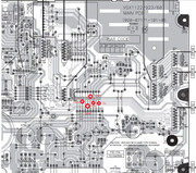
Boy, it seems like the more I try to get caught up on things the busier I get. Well lets see if I can remember where we were. So the main relay is latching despite some funny testing earlier. So now you need to do some voltage testing. But you have to be sure that main replay is latching on to do these tests. If is not or is erratic then you will have to jump the relay to be sure it is on. So turn it on and be sure you hear that main relay latch. Set your DMM on DC voltage. I have marked on the image of the main board where to test. I believe you can get at it without having any boards removed. If you cannot then you may have to remove some boards and then the main relay will probably have to be jumped. So first you are testing the + and - 5v and + and - 12v. Give me the exact voltage readings you get. It is a little hard to read so the circles, going left to right are: +12v,Gnd,-12v,+5v and -5v.  |
|
|
|
Post by tibimakai on Jan 13, 2015 13:24:15 GMT -5
Relay latches, only if I hold the power button for like 10 seconds. Then it's on, showing Power on, on the display.
Yesterday, I have picked up a "broken"(customer returned receiver, from Newegg) Onkyo TX-SR333. When powered on, it did the right clickings, but nothing would show up on the display.
When I opened it up, a connector that goes to the front board, it was not connected.(!) Easy repair.
After connecting it, it was working as it should.
|
|
|
|
Post by tibimakai on Jan 15, 2015 23:26:08 GMT -5
Here are the measurements:
-5V= -4.922V
+5V= 5.019V
-12V= -12.02V
+12V= 12.14V
Fluke 87V
|
|
|
|
Post by tibimakai on Jan 20, 2015 1:14:05 GMT -5
Any input?
|
|
|
|
Post by mastertech on Jan 22, 2015 23:44:13 GMT -5
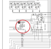
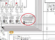
The reason it takes me so long to get back to you with the next step is because this thread is getting dragged out to much. Usually when I help someone, I give them a test to make and they get back with the results either in a couple hours or next day at the latest. But when days go by before I get the results from the test I suggest, I have to go back and reread where everything is at because I have been involved in 10 or 20 other things in between. So I think in order for us to make any progress on this unit you are going to have to dedicate some time to do the test right away and get back with the results. Because if I have to go back and reread every time, I do not have that kind of time to invest in this one. So next, on the same board you need to check for +12v at CN801 and then check for the + and - voltage at CP403. Let me know what you get.   |
|
|
|
Post by tibimakai on Jan 23, 2015 11:25:56 GMT -5
That situation, it was valid for the holidays, now I'm here.
Afternoon, I will take these measurements.
Thanks
|
|
|
|
Post by mastertech on Jan 23, 2015 12:17:31 GMT -5
Agreed.  |
|
|
|
Post by tibimakai on Jan 23, 2015 23:57:59 GMT -5
The first one shows 12V= 13.83V
The second is: High is 60.55V
Low is -60.55V
|
|
|
|
Post by mastertech on Jan 24, 2015 0:03:24 GMT -5
Ok. Tomorrow I am going to go over all the data so far and see if we can find out what is going on. As you indicated in the beginning, all the voltages seem ok and none of the protection circuits seem to be triggered.
|
|
|
|
Post by tibimakai on Jan 27, 2015 17:44:41 GMT -5
Any news?
|
|
|
|
Post by tibimakai on Jan 30, 2015 11:18:43 GMT -5
I'm still here.
|
|
|
|
Post by mastertech on Jan 30, 2015 16:00:59 GMT -5
I have actually been looking over a VS60 I have here for parts to see how you need to do some next tests. It looks like I will need you to make some tests on the MCU on the front board but it will have to be powered up, well enough to have the main relay on as it does. It looks like you will have to remove the front panel and detach the board to get to the back side. Then you will have to test right on the pins of ic3004. Are you able to do this?
|
|
|
|
Post by mastertech on Jan 30, 2015 16:01:36 GMT -5
Curious, where are you located?
|
|
|
|
Post by tibimakai on Jan 31, 2015 14:56:30 GMT -5
I'm in Los Angeles/Monrovia.
I can take it apart, no problem.
I already did some measurements on that board around the CPU.
There is the reset IC as well.
VSX60, is pretty much the same thing, it just has some extra stuff, since it's a higher trim model.
|
|
|
|
Post by mastertech on Feb 1, 2015 13:06:13 GMT -5
Ok, then I need you to do some tests on ic3004 while it is powered up. Try to test on the pin where it enters the ic so we know the solder joint is also ok. Try not to slip and give me your results for the following pins.
2,3,8,9,14,17,18,19,20,21,40,45,55,58,64,70,71,72,78,80,81,82,83,84,85,86,87,89.
|
|