|
|
Post by gjaky on Feb 4, 2018 17:05:08 GMT -5
As for that inductor, all I suggest for an upgrade is one that runs cooler and won't turn brown and become resistive after a few thousand hours of operation. Which seems to be what happens to the original axial leaded ones with white bodies. I don't know, but pulled out two random coils, one with brown end and the other with cream end. They both measured the same for inductance and resistance too. Instead, I've yet to see a classic neckboard that do not need solder rework on the power resistor's legs -even if they are not seem to be burned. |
|
|
|
Post by thelasttubewarrior on Feb 6, 2018 8:42:02 GMT -5
Still waiting for connectors to arrive. But, happily, yesterday I picked up two brand new, never used PT22 green tubes with standard phosphor. Plus a brand new, unused blue Mikado LUG.
|
|
|
|
Post by jbmeyer13 on Feb 6, 2018 10:08:45 GMT -5
So personally i role my eyes everytime i read about change the caps here and there.. I experienced Chris Stephens HVPS mods that introduced heavy crosstalk, like WTF how can nobody have noticed. Thats the level most mods have, so like i mentioned before, go find a old Marquee Electrohome build, actually 1996-1997 might be the best ones ever, from there it got messy. Well technically Chris used a bunch (6 or 7) 560uf wet tantalum caps and I substituted those for a giant poly film cap. It's sheer size might have contributed to the fact that it was a giant tuning fork..lol Similar to when I put ferrite chokes on the leads of the wet tants on a set of VNB's which created all kinds of ghosting. Some things seem good in theory but just don't work out that way in reality. A matched set of stock neck cards is more useful than just about any mod. The only mod that ever really made a noticeable BW gain was MP's mini board for the 02/03 VIM in conjunction with upgraded VIM cables. Chris Stephens used like $5K worth of wet tantalums and I'm sure that due to the higher quality of those caps helped make things more stable with better filtering but it definitely didn't boost the BW. Back then they were only running 1080p/48 so it's not even close to what we run now. Would be curious to get my hands on one of those Reference Imaging sets but haven't seen one for sale in 7-8 yrs. |
|
|
|
Post by thelasttubewarrior on Feb 6, 2018 13:13:21 GMT -5
Adding inductance (ferrite beads) to the leads of a capacitor make an LC filter network. Is it any wonder that it caused ghosting at the resultant resonant frequency?
Never use caps to tame an inductor, either, unless you WANT a resonant circuit.
Add resistance instead. Lowers the Q.
|
|
|
|
Post by jbmeyer13 on Feb 6, 2018 14:13:30 GMT -5
Adding inductance (ferrite beads) to the leads of a capacitor make an LC filter network. Is it any wonder that it caused ghosting at the resultant resonant frequency? Never use caps to tame an inductor, either, unless you WANT a resonant circuit. Add resistance instead. Lowers the Q. The axial lead wet tantalum caps that Chris suggested are huge and those leads could potentially act as antennas and ferrite chokes are supposed to prevent such a scenario. I did not factor in the material composition or size when trying this so it was a very "by the seat of my pants approach". The idea was for the ferrite choke to suppress high frequency noise and I understood that the ferrite creates an inductor with a low Q and could be used over the leads to tame parasitic oscillation. This was based on reading theory but not having training or practical experience in the field.
|
|
|
|
Post by thelasttubewarrior on Feb 6, 2018 22:38:48 GMT -5
Be aware of the pitfall of low ESR capacitors. Which is...they lower the circuit impedance as seen by the power supply, and this causes the startup inrush current to become larger.
Everything is a tradeoff. Lower ESR caps mean higher inrush current. Will your power supply handle it?
|
|
|
|
Post by gjaky on Feb 10, 2018 15:27:10 GMT -5
I did some experiments on the HDM regarding the retrace times and raster ringing.
The goal is to optimize 1080p 72Hz (2400 total horizontal pixels)
The idea behind this is the following: On stock machines, with maintaining the 2400 total H pixels it is possible to project an image without much ringing only by shifting the image to the right on the raster, which (the raster) is considerably larger than the real screen width. This needs careful setup procedure and generally stresses the electronics more as the raster in horizontal plane much larger than the projected image. To overcome this the retrace time of the H deflection should be altered (lengthen) so the active picture width is just fitting in the active part of the raster. We all know that the raster ringing is in close relation with the retrace time so lengthening the retrace time would improve ringing behavior, plus gaining simpler setup and a cooler running HDM. Now as already known it IS possible to project the 2400 wide frame without ringing so the only question remained is how to get the electronics do what we want...
First I wanted to see if the "blanking time" is dynamically adopted or they are preset values. For this I removed C8 and C13 capacitors from the HDM (these are the capacitors for the "long retrace" mode). By toggling between long and short retrace did result in a major crop on the left while in long retrace. If the blanking time would be dynamically adopted both setting would look the same, this did not happen so this is sad.
On the next step I reinstalled C8 (only) and intentionally shorted the contacts of RL2 (this does the changeover of long / short retrace), this forced the HDM to operate in a "middle" retrace mode as there was added capacitance to the deflection core but only half of that in long retrace, while the system thought it is operating in short retrace mode.
This way the active image filled better the raster (less H-width was needed to fill the screen) but there was still some ringing in the raster along with some spare space to shift out the image from the ringing area. One step closer, this is good!
As it looks more capacitance should be added for the perfect result, C8 and C13 are 3.3nF each so I think with another 1..2nF added capacitance the goal could be achieved.
|
|
|
|
Post by stridsvognen on Feb 13, 2018 9:50:23 GMT -5
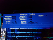
Remember that the porch timings is also used to shift the active image as far right as possible, how do you get around the centering of the active image.?  |
|
|
|
Post by gjaky on Feb 13, 2018 17:26:14 GMT -5
Remember that the porch timings is also used to shift the active image as far right as possible, how do you get around the centering of the active image.?  By setting the HDM to a longer retrace inherently reduces ringing, therefore no need to trick with porches. Attachments:
|
|
|
|
Post by thelasttubewarrior on Feb 13, 2018 19:53:53 GMT -5
I would suggest that you evaluate the capacitances of the HDM and the inductances of the deflection coils with an eye toward adjusting the capacitance values to achieve resonance at 1080p72, as the HDM and deflection coils form an RLC resonant circuit, which, assuming that this doesn't have any negative consequences such as promoting ringing, should make for a cooler running and optimized HDM.
The same thing can be done for the focus system as well. I think I still have my notes as to the required FGM cap changes that would put the focus system into resonance at the desired scan rate.
|
|
|
|
Post by gjaky on Feb 14, 2018 4:22:16 GMT -5
I would suggest that you evaluate the capacitances of the HDM and the inductances of the deflection coils with an eye toward adjusting the capacitance values to achieve resonance at 1080p72, as the HDM and deflection coils form an RLC resonant circuit, which, assuming that this doesn't have any negative consequences such as promoting ringing, should make for a cooler running and optimized HDM. The same thing can be done for the focus system as well. I think I still have my notes as to the required FGM cap changes that would put the focus system into resonance at the desired scan rate. The HDM is not really working that way, I mean the only thing is resonant in the HDM is the retrace time, but this is what I am actually doing: optimizing the retrace time for the given display timings. Ringing on the other hand is a result (a series) of parasitic effects around the deflection core, very difficult to measure and even more difficult to improve in a reasonable extent. As for the FGM I've already done my homework: C119, C219, C319 caps should be altered from 68nF down to 33-47nF for better efficiency for 82kHz scanrate. |
|
|
|
Post by stridsvognen on Apr 3, 2018 17:51:21 GMT -5
Just got a set of the latest and greatest MP mods with the mail man today.
I started testing the vim and moome card together, wich to my surprise actually worked, it had about dubble the output of my own vim and moome, so had to run about ½ contrast, and got around 9fl before blooming got to bad, vs 11-12fl on my own set.
I then put in the MP neckboards, and it fired up, measured 7fl on the complete setup with aceptable blooming, but while togeling around the testpatterns i noticed a odd behavior, it would do a well behaved gray scale if running single 20% windows from 0-100% ire, but on a step pattern it went way off, and putting up a full white field, the green cut off, like a limiter kicking in, it got worse during heatup, and it started clicking and flashing so had to turn it off.
I did later fire it up a a much lower contrast setting, i did not measure, but ill guess 4-5fl, and it did not freak out, but somewhat cut down the output on green when running a full white field.
So the conclution is that MP has absolutely no idea what he is douing, its a serious pile of sloppy work, dirty boards and potting who makes it impossible to save or repair any of the boards, the vim seems to be the best board, nothing special, its a 03vim with a miniboard, its not behaving very linear on the ecrabb pattern, and seems to have a noise issue, specially on red wich blooms early, wich is not normal, gren should come way before.
This was a set made after he claimed to have corrected the issues that had been troubeling on previous mods, this specifik sample have been sent back for fixing, without making it a usefull set, a set of standard boards will be a much better option.
Lightoutput on this set matches pretty much what i have seen before, less than a standard projector, problem is a mix of both vim and neckbaoards, so its not been possible to use one or another in combination with other boards with satisfying results.
On the positive side there was no issues on a black tube face as on previous mods, but was not able to get any usefull opinion on real movie material due to the low light output and odd behavior of the neckboard.
|
|
|
|
Post by stridsvognen on Apr 7, 2018 7:52:12 GMT -5
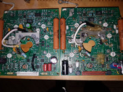
Here is a picture of the 2 different neckboards, the left is the ones i run in my projector daily, the right one is the latest MP mods one, wich ill warn anyone agains trying out if they value their projector.  |
|
|
|
Post by barclay66 on Apr 9, 2018 3:52:56 GMT -5
Wow! What a butchered mess!
|
|
|
|
Post by stridsvognen on Apr 9, 2018 11:03:14 GMT -5
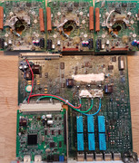
Sadly there is no saving those boards.. Also a 03vim has been lost to the butchers handywork.  |
|