nashou
Unmoderated Off Topic
Tech in Training.....
Posts: 1,239 
|
Post by nashou on Feb 7, 2014 22:30:41 GMT -5
Ok Mac onto receiver number 2.
No power and no lights at all, tested rectifier( D3701) on power board which i removed from the unit and it showed about 166 VDC so that seems fine.
the 5 volt
Not sure where else to check . I think I'll have to plug that board back in before going forward correct?
Athanasios
|
|
|
|
Post by mastertech on Feb 8, 2014 12:11:33 GMT -5
Ok, lets try this first. Make sure all boards are in and connected. Press and hold the "tone control and info" buttons. While holding, press and release the "main zone" button while keep holding the other 2 buttons for another 5 seconds. Let me know if you get anything.
|
|
nashou
Unmoderated Off Topic
Tech in Training.....
Posts: 1,239 
|
Post by nashou on Feb 8, 2014 13:31:16 GMT -5
Ok, lets try this first. Make sure all boards are in and connected. Press and hold the "tone control and info" buttons. While holding, press and release the "main zone" button while keep holding the other 2 buttons for another 5 seconds. Let me know if you get anything. I tired that after I posted and no go. I downloaded the service manual from HIFi Engine. I think it may be the transformer. Not sure what the voltages should be on the two small PCB boards that are connected on either side of the transformer as i can't figure out the voltage locations from the schematic. I am at work now so this will have to wait till later today.    |
|
|
|
Post by mastertech on Feb 8, 2014 15:24:50 GMT -5
Yamaha really does have some very strange circuit designs and seem more complicated then required. Anyways, the AC-DC converter board(the one the AC cord connects to, locate connector CB376. I hate when the schematic does not give me pin numbers. This is where your +5v standby comes from. Is this where you have already checked?
|
|
nashou
Unmoderated Off Topic
Tech in Training.....
Posts: 1,239 
|
Post by nashou on Feb 8, 2014 16:54:30 GMT -5
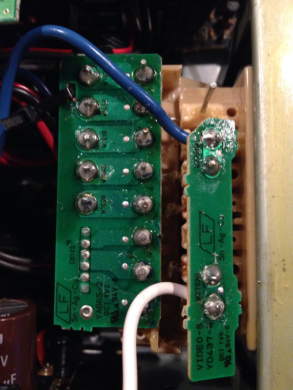
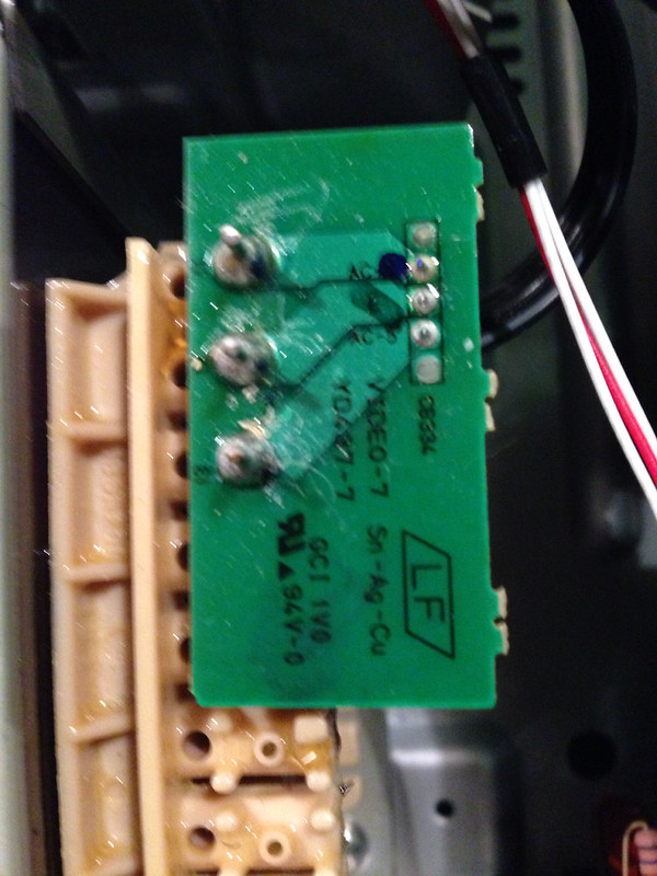
Yep the 5 volts is there. That board seems to be ok I think. Now the small board connected to the transformer in the last picture shows on the PCB AC +5, E. and AC - 5. Not sure how to measure this and I tried it two ways and both got the same results. I touched the E with the Black probe and the red to either pin and got a very low reading like .0004. but if I lift the red probe from either pin and leave the black to E i get a 3.4 AC reading? Now that is weird to me if I get a reading with the red probe not touching. both probes not touching anything do have some low AC reading which I think is normal.
Nashou
|
|
|
|
Post by mastertech on Feb 8, 2014 17:26:15 GMT -5
Why would you think there should be voltage there?
|
|
nashou
Unmoderated Off Topic
Tech in Training.....
Posts: 1,239 
|
Post by nashou on Feb 8, 2014 20:01:59 GMT -5
Why would you think there should be voltage there? Just assumed. Nashou |
|
|
|
Post by mastertech on Feb 8, 2014 20:22:36 GMT -5
Unless the main relay is latching on then there will not be any power there. And you indicated you had nothing, no power, no lights, no clicks.
You next need to go to the video 3 board. It is the one the harness from CB376 goes to. On that board look for connector CB375. Again there are no pin numbers on the schematic so look at the diagram on page 145, if your manual is the same as mine. Using the DGND for neg, test the other pins with DMM on DC voltage and give me all the readings you get, calling the +3.3 pin 1. Check that other connection there with the 5.5v just to be sure we still have it on this board.
|
|
nashou
Unmoderated Off Topic
Tech in Training.....
Posts: 1,239 
|
Post by nashou on Feb 8, 2014 20:37:56 GMT -5
no voltage on any. all read .07x or lower.
The 5.57 volts is on the other connector
|
|
|
|
Post by mastertech on Feb 8, 2014 20:46:50 GMT -5
Ok, go back to the AC-DC convertor board. Locate ic374. Check for some DC voltage on the 2 pins that come from the diode bridge assy.
Edit: Wait, let me look at something here. You can check it anyways if you want.
|
|
|
|
Post by mastertech on Feb 8, 2014 20:58:30 GMT -5
Ok, being no +3.3m you need to go to the digital board, try to locate a 4 pin regulator, ic97. If you can get at it to test it with it plugged in, DMM on DC voltage, pin 2 for gnd, pins 1 and 4 = +5.5v and pin 3 = +3.3v
|
|
nashou
Unmoderated Off Topic
Tech in Training.....
Posts: 1,239 
|
Post by nashou on Feb 8, 2014 21:03:39 GMT -5
Ok, go back to the AC-DC convertor board. Locate ic374. Check for some DC voltage on the 2 pins that come from the diode bridge assy. Edit: Wait, let me look at something here. You can check it anyways if you want. Pin 1 very low DC almost negligible . Pin 2= 16.7 3 is grnd 4 nothing the rest 173 |
|
|
|
Post by mastertech on Feb 8, 2014 21:05:41 GMT -5
.
|
|
nashou
Unmoderated Off Topic
Tech in Training.....
Posts: 1,239 
|
Post by nashou on Feb 8, 2014 21:06:01 GMT -5
Ok, being no +3.3m you need to go to the digital board, try to locate a 4 pin regulator, ic97. If you can get at it to test it with it plugged in, DMM on DC voltage, pin 2 for gnd, pins 1 and 4 = +5.5v and pin 3 = +3.3v Let me find that board. |
|
|
|
Post by mastertech on Feb 8, 2014 21:12:11 GMT -5
Ok, being no +3.3m you need to go to the digital board, try to locate a 4 pin regulator, ic97. If you can get at it to test it with it plugged in, DMM on DC voltage, pin 2 for gnd, pins 1 and 4 = +5.5v and pin 3 = +3.3v Let me find that board. I believe it is the HDMI board. |
|