|
|
Post by justgreg on Feb 24, 2014 15:46:47 GMT -5
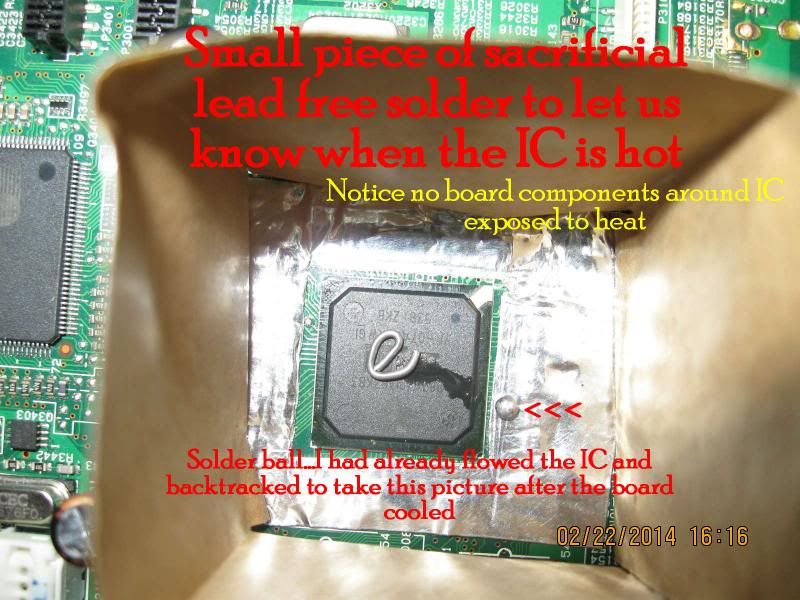 The picture markup pretty much says it all but this pic was taken right after reflowing. I was more worried about shaking hands than bumping the board. The sides of the oven absorbed all of my shakiness thankfully. If the IC moved even a little it would have required a re-work instead of a re-flow. |
|
|
|
Post by justgreg on Feb 24, 2014 15:49:22 GMT -5
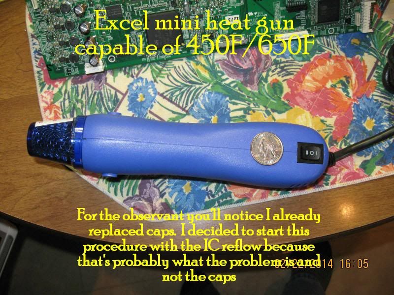 I picked this up at a local electronics distributor. They usually have crazy high prices for everything so I was pleasantly surprised to get this for $20. It's small, light, powerful and best of all, the nozzle fits inside the oven. |
|
|
|
Post by justgreg on Feb 24, 2014 15:52:45 GMT -5
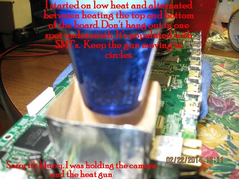 Holding the camera and the heat gun at the same time. Not recommended but you won't have to do that if you use this procedure. This step was a nail biter because I had a LOT of missing information as to how long or how much I should heat the IC. I was worried that any second I would see the IC fly off the pad. FYI I chose to use high quality low ESR radial caps for replacements of the SMD packages because this board is a known Onkyo issue and radials will allow for visual inspection. SMD's don't bulge or 'pop up' when bad. They 'can' blow up...but that's another story. |
|
|
|
Post by justgreg on Feb 24, 2014 15:55:27 GMT -5
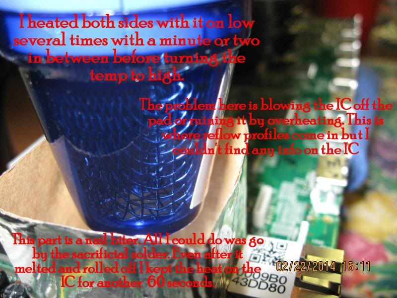 What a cocky bugger eh? I managed to get a nice clear pic while juggling everything. This was taken with the gun on high (around 650F) and inserted into the oven more than the pre-heat step. The tattle-tale solder had melted and rolled off onto the IC mask at this point. I held it on there for another 60 very long seconds. |
|
|
|
Post by justgreg on Feb 24, 2014 16:01:25 GMT -5
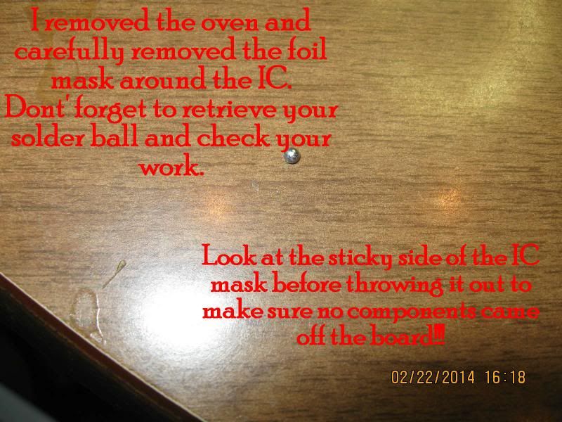 And that's it. Allow the board to either cool without taking the surface temp down slowly or not, that's your call. I chose to cook it down slowly(ish). Reinstall the board or replace caps at this point. I had already replaced the caps and had nothing to lose by going right into the reflow. If you have a working HDMI board but want to reflow as a precaution I would reflow first and reinstall the board to make sure it still works before tackling the caps. One note about the two grey cables on top of the board; don't forget to press down on top of one half of the connector. The wires will slide right in if you get it right. You shouldn't have veins popping out on your arms (or forehead) to do this but the net is full of stories of people fighting these two connectors and breaking them. Comments and constructive criticism welcome. |
|
nashou
Unmoderated Off Topic
Tech in Training.....
Posts: 1,239 
|
Post by nashou on Feb 24, 2014 19:03:50 GMT -5
Nice write up Greg!!
Yeah with those heat guns you need to do the heat blocks.
If your going to get into this more, that unit I got is sweet along with some Chip Quik Low temp solder chip removal is a snap!!
Nashou
|
|
|
|
Post by Admin on Feb 25, 2014 9:34:37 GMT -5
justgreg: Nice write up. Would you mind if I split off your tutorial into a separate thread so it is easier to find rather then be buried in here?
|
|
|
|
Post by justgreg on Feb 25, 2014 13:08:35 GMT -5
Hiya Admin. Sure please feel free to break it out. Mac and I briefly touched on doing that before I posted it. Thanks Nash! I'm seriously thinking of buying the same station you did. Great price too!! I have to find a way to justify it to the wifey. I know I know....(insert sound of whip). Also please feel free to add any comments or improvements to my admittedly over simplified procedure. I was limited in the things I could try (and I had a ton of ideas) by the fact I only have the one board. I thought I had an auction for 4 in the bag that needed repair but I got massively sniped at the last second. The dude REALLY wanted them apparently!  I'm pulling together the parts to try one of my concepts....a wide jawed 'clamp' with a PID controlled heated block that sits on top of the IC. This is NOT ideal because the heat should be applied directly to the BGA area but...I have the stuff handy and I gotta try it. <evil grin> Of course I'm not going to try it on the 708...I have an old LCD TV I've been torturing for some time now whilst learning. I can't believe it's still working after what I've done to it.  Disclaimer: To anyone that's going to attempt this repair using my process as a roadmap: Keep in mind you could gork your board by overheating the IC, or otherwise screw up the board. If you don't totally destroy it you should be aware that you're going to have to pay someone more than a 'normal' repair to fix it; or you'll have to replace it. I look at it as a bit like investing in the stock market....if you can't afford to lose it, don't do it.  Attachments:
|
|
|
|
Post by justgreg on Feb 25, 2014 21:39:14 GMT -5
2/25/14 FOLLOWUP: I've had to reflow the IC when I lost audio again after two days of heating and cooling. (on/standby). I believe it failed because I was too conservative with the high temp. phase of the procedure. Regardless of the level of sophistication of the gear I'm using (or lack thereof) from what I've been reading this can happen if doing reflow and not full-on rework, so I won't blame it entirely on my home brew approach. I also revised my 'oven' design. In Oven Rev. 2.0 I made the sides about .75in/19mm and flared them outward from the base about 33 deg. The goal this time around was: 1) Channel more hot air to the BGA joint area 2) Put less heat onto the top of the chip I ran it for 5 hours at 3/4 max volume (my wife wasn't home, but now my dog hates me) and ran it for a total of 10 hours before shutting it down for the day. One interesting observation; I noticed that just prior to totally losing all audio, other than having to leave the receiver on until the IC heated up, was the LFE output greatly diminished prior to not hearing the power-on relay latch (with resulting total loss of audio). If your bass isn't what it used to be and you're trying to compensate with adjustments you've never had to make before and it still isn't right, I'd definitely suspect the TI HDMI board IC and think about reflowing. Of course it could be something totally unrelated to the HDMI board but at my experience level that's where I"d start. Regardless, whether you're reflowing for the first time or revisiting a previous attempt, don't forget to apply No Clean liquid flux first. 2/26/14 As soon as I got up for the day the first thing I did even before grabbing a cup of coffee (yeah...I need a life) was power up the 708 while it was stone cold to see if the repair stuck over night. It's winter here and I turn the thermostat down to 65F at night so the receiver was quite cold. The relays latched in a timely manner after it performed it's POST and went right to producing good output across all channels with excellent LFE effects. This is hardly the true test of time given my first attempt went wonky in two days but stay tuned. I'll definitely let you know if or when it goes out again. If it does, I won't try to reflow again because obviously the existing BGA solder isn't up to the task. It took me some time to realize I was asking a lot of these BGA solder joints (yeah...umma rookie). After all, they failed for a reason to begin with right? If it does fail again a full rework is indicated. I'll have no choice but to either buy the gear or bite the bullet and send it out for full blown rework to someone who does have the goods. (Nash?..buddy?..pal?)  On a related note, I've been sourcing PC based endoscopic digital microscopes with still and video capabilities to see if I can see what the manufacturers see when they inspect BGA solder joints, at least the outer perimeter ones. I found one with X/Y/Z micrometer like adjustments, manually focused, (as opposed to fixed) LED lit, contact distance resolving, a mini angled mirror, and best of all, it's very inexpensive so if it doesn't do a great job I won't be out food for a day (month?). Seeing as I don't know anyone with access to an X-Ray machine, looking at the perimeter joints is as close as I'm going to get to seeing 'under the hood'. It's the joints I CAN'T see that are going to trip the trigger on my OCD and bug the heck out of me!  |
|
|
|
Post by justgreg on Mar 2, 2014 18:08:19 GMT -5
Well it's March 2nd and it's still working. I left the cover off the whole time because I didn't know if I'd have to get back in there. I just put the cover on so we'll see how it goes. I also have to study the service drawings to see if the fan in there is supposed to be on all the time or is thermocouple dependent. I haven't seen it start yet; even after 10 hours of on time with volume at around 75.
I'm also going to add non conductive UHMW board edge reinforcement (0.250"square stock) because the board isn't supported on one entire long edge. To my way of thinking, this could and probably does lead to a lot of board 'ribboning' during heating and cooling. More to come on that.
|
|
|
|
Post by justgreg on Mar 15, 2014 23:57:29 GMT -5
March 15th and still working.
|
|
|
|
Post by justgreg on Mar 25, 2014 21:32:16 GMT -5
March 25th and still working BUT...I think I'm detecting a loss of low frequency. If I lose all LFE and/or all audio again I'll have no choice but to completely remove the DTS chip and reball it. If that happens I won't generate another procedure but will just add a link to an excellent youtube vid someone else has already made. I'm not adding it now because this sticky is all about DIY reflowing whereas reballing requires higher level equipment not generally found in a DIY-ers toolbox. EDIT: 3/30/14 Man is my face red. Turns out I had NO LFE, not just diminished. I found the 'solution' after retrieving my dogs ball where she dropped it in the corner near the sub. And the reason?...we lost power in the house a week ago before I noticed poor bass output and the surge protector powering the sub had delatched as part of it's protect mode. When the coupling relay lost power the sub of course was without mains. I poked the power button with my cane and 'voila...  The most important thing however is that my DIY BGA reflow is still holding. |
|
|
|
Post by justgreg on May 16, 2014 7:12:25 GMT -5
Ok. Here we are at May 16 and I've had to put heat to the DTS chip. So although my home brew attempt at a lasting fix worked for a couple months, it shouldn't be considered a permanent repair if you follow my procedure. There are many variables involved but the biggest consideration should be given to the quality of the solder used by the manufacturer, and the BGA process itself.
Because the HDMI boards are becoming scarce due to repair shops buying up all available boards to fix and sell, you'll have to determine if you want to DIY reflow or pay them the $80-ish for one they've repaired. Some repairers are installing a daughter board at the time of repair that's supposed to enhance the boards capabilities so if you have ~$80+shipping, that may be the way to go. Keep in mind not all repair shops are created equal so ask about a warranty if you either send them your HDMI board or buy one they have ready to ship.
|
|
|
|
Post by gjaky on May 16, 2014 11:34:27 GMT -5
Haven't you tried to fabricate a small heatsink on that DTS chip if it gets that hot? A good cooling is always handy for prevention.
|
|
|
|
Post by justgreg on May 27, 2014 2:47:14 GMT -5
I haven't attached a fan because the chip is quite small and truthfully I haven't had time to either locate one with a heatsink, or to fabricate a remote fan and ductwork. There are many possible ways to provide active cooling however I believe based on my experiences with this chip/board, and the 100's of failures reported widely across the internet that the problem lies with the solder and/or BGA manufacturing process. I'd hate go through all the trouble to provide cooling only to end up back at square one. The system has been quite stable for weeks now but when it fails again (I have no doubts it will), I'll have the chip reballed and be done with it.
|
|