|
|
Post by justgreg on Mar 4, 2014 13:38:50 GMT -5
Thanks for the reply again Mac,
K. Just to clarify because I know bupkus right now about PS's... Is one of those a neg and I test between the two or do I need to find a neg and test both? I'd already tested for DC before starting this post but I had pulled ground from one of the tinned mounting holes the line in ground lug is screwed down to. Is that a sufficient ground or do PS's have a discreet ground?
The only voltage I was able to find on this board was in the AC section but again, I might have not been doing it right.
|
|
|
|
Post by justgreg on Mar 3, 2014 20:52:27 GMT -5
Correct again Oh Enlightened One.  I hadn't thought to even look anywhere downstream. (One of the dangers of learning from YouTube vids!!) I should at least get +5v on one pin thought right? PSon would come from farther downstream but would still have to come back to the tap at the SMPS I'm thinking. Unless I didn't catch neg from an isolated part of the circuit??? |
|
|
|
Post by justgreg on Mar 3, 2014 19:37:56 GMT -5
The dang thing is so cheap the pinouts aren't even marked on the board so I can short PSon and +5V to test it better.
|
|
|
|
Post by justgreg on Mar 3, 2014 19:35:13 GMT -5
 Sorry bout that. |
|
|
|
Post by justgreg on Mar 3, 2014 19:13:22 GMT -5
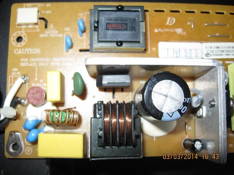 AC mains section. Yup, I checked the fuse and it's good. Note the protection caps. I got nothing testing these with an ESR meter or my Fluke 233 on cap setting. (tested in circuit). |
|
|
|
Post by justgreg on Mar 3, 2014 19:10:07 GMT -5
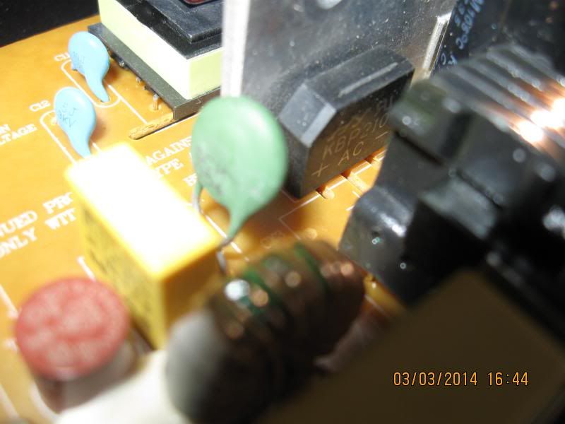 The bridge rectifier section. Should these only (best) be tested out of circuit? |
|
|
|
Post by justgreg on Mar 3, 2014 19:08:36 GMT -5
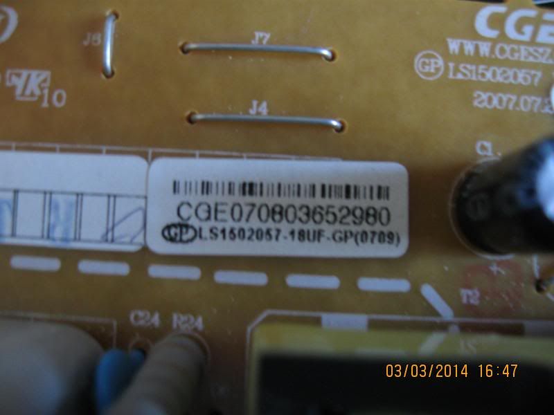 SMPS part number label. I couldn't find anything online for this but given the el-cheapo brand of this set that's not surprising. |
|
|
|
Post by justgreg on Mar 3, 2014 19:02:36 GMT -5
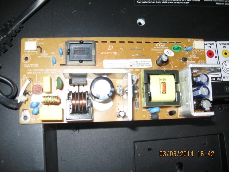
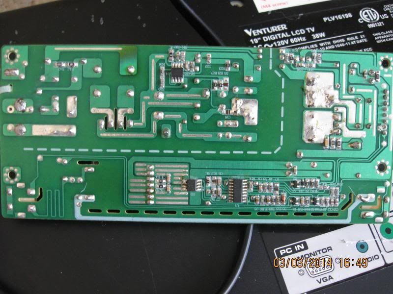 Back of SMPS. Let me know if you need a better pic or closer and break it into left and right |
|
|
|
Post by justgreg on Mar 3, 2014 18:41:43 GMT -5
Sorry for not getting back to this sooner. I didn't know the home button would work. That's just as easy and I know you're juggling a lot. Thanks for the workaround.
|
|
|
|
Post by justgreg on Mar 3, 2014 1:17:38 GMT -5
Hmmmm. My earlier reply didn't stick. <shrug>
Anyway, I have pix but the batteries died in the camera so will put them up later today when I get up. Only have a couple more days to play anyway and if I don't fix it it will have to wait...Thursday (gulp) I get spinal fusion surgery. humenahumenahumana. Nervous? Yup!!!!
|
|
|
|
Post by justgreg on Mar 2, 2014 18:08:19 GMT -5
Well it's March 2nd and it's still working. I left the cover off the whole time because I didn't know if I'd have to get back in there. I just put the cover on so we'll see how it goes. I also have to study the service drawings to see if the fan in there is supposed to be on all the time or is thermocouple dependent. I haven't seen it start yet; even after 10 hours of on time with volume at around 75.
I'm also going to add non conductive UHMW board edge reinforcement (0.250"square stock) because the board isn't supported on one entire long edge. To my way of thinking, this could and probably does lead to a lot of board 'ribboning' during heating and cooling. More to come on that.
|
|
|
|
Post by justgreg on Mar 2, 2014 17:56:01 GMT -5
To close this, eBay honored their Money Back Guarantee and I'm getting a full refund with shipping.
I was going to use the money to get another TX-NR708 to fix with the refund but I missed the %$#^@!# bid window doing Honey-Do crap!!! GAHHHHHHHHH! It sold for ~$40 and ~$35 shipping. I most wanted it for the remote and the Audyesse calibration mic for the 708 I already have that I fixed. Ah well.
Yeah I learned the same lesson about rating scores because of this. I hate to be that way because it makes it hard for a new Seller to get started but the jerks, as usual, ruin it for everybody.
I'm getting a prepaid shipping label from eBay to send the thing back to the guy. His last comments to me before I told him I wouldn't be communicating with him any more was to accuse me of breaking it on purpose. For what purpose I have no flippin idea. I really wanted that Panny BR player because it had options to output in checkerboard format which my Samsung HL67A750 can only accept. Gonna look for another one tho. I'm just glad it's over and settled.
|
|
|
|
Post by justgreg on Mar 1, 2014 15:25:18 GMT -5
Guys
I'm trying to repair a power supply for an old(er) 22" Venturer TV/monitor by Venturer Electronics Inc. out of Ontario. Model: PLV 16198 Manuf. date: October '07.
I've been unable to find a schematic for this thing but I 'think' it's a big box electronics/retailer offering like BestBuy or Walphart.
I'm brandy new to power supply testing so any advice greatly appreciated. I'm still also learning how to test components; FETS,bridge rectifiers, etc. I'm most proficient at testing diodes, caps, resistors, and transistors. I have ac mains up to the dc conversion section but no dc out. All the caps test OK with my Fluke 233 and an ESR meter and none are leaking/bloated.
Methinks I can't see the treefor the forest and am over thinking this tho. lol
I also could use a little enlightenment on how to test X/Y capacitors. There are a couple/three in the ac section but they were OL and no ESR.
Thanks guys!
|
|
|
|
Post by justgreg on Feb 26, 2014 3:59:38 GMT -5
And?....don't leave a brother hangin! So you lucked out and didn't have to change out IPM's huh? (So far). Those are a special treat. Like Mac said earlier, drawings are hard to find so to get part numbers off the IPM's you have to remove it from the board first but the heatsink screws go through the IPM, and the heads are under the chip, and the chip is soldered in. Muaahaaaaahaaaa! Without having any drawings ya got no p/n so can't order parts until ya take the dang thing off the board. Did em both on a 42" Insignia I snagged a couple years ago for $35. I think I might have already mentioned this before tho. I need a flash jig to update the firmware to fix the sparklies and mal discharge but I'm not putting any more $ into it. Anyone have one I can borrow?  LG made a lot of the plasma chassis for different manufacturers didn't they? |
|
|
|
Post by justgreg on Feb 25, 2014 21:39:14 GMT -5
2/25/14 FOLLOWUP: I've had to reflow the IC when I lost audio again after two days of heating and cooling. (on/standby). I believe it failed because I was too conservative with the high temp. phase of the procedure. Regardless of the level of sophistication of the gear I'm using (or lack thereof) from what I've been reading this can happen if doing reflow and not full-on rework, so I won't blame it entirely on my home brew approach. I also revised my 'oven' design. In Oven Rev. 2.0 I made the sides about .75in/19mm and flared them outward from the base about 33 deg. The goal this time around was: 1) Channel more hot air to the BGA joint area 2) Put less heat onto the top of the chip I ran it for 5 hours at 3/4 max volume (my wife wasn't home, but now my dog hates me) and ran it for a total of 10 hours before shutting it down for the day. One interesting observation; I noticed that just prior to totally losing all audio, other than having to leave the receiver on until the IC heated up, was the LFE output greatly diminished prior to not hearing the power-on relay latch (with resulting total loss of audio). If your bass isn't what it used to be and you're trying to compensate with adjustments you've never had to make before and it still isn't right, I'd definitely suspect the TI HDMI board IC and think about reflowing. Of course it could be something totally unrelated to the HDMI board but at my experience level that's where I"d start. Regardless, whether you're reflowing for the first time or revisiting a previous attempt, don't forget to apply No Clean liquid flux first. 2/26/14 As soon as I got up for the day the first thing I did even before grabbing a cup of coffee (yeah...I need a life) was power up the 708 while it was stone cold to see if the repair stuck over night. It's winter here and I turn the thermostat down to 65F at night so the receiver was quite cold. The relays latched in a timely manner after it performed it's POST and went right to producing good output across all channels with excellent LFE effects. This is hardly the true test of time given my first attempt went wonky in two days but stay tuned. I'll definitely let you know if or when it goes out again. If it does, I won't try to reflow again because obviously the existing BGA solder isn't up to the task. It took me some time to realize I was asking a lot of these BGA solder joints (yeah...umma rookie). After all, they failed for a reason to begin with right? If it does fail again a full rework is indicated. I'll have no choice but to either buy the gear or bite the bullet and send it out for full blown rework to someone who does have the goods. (Nash?..buddy?..pal?) On a related note, I've been sourcing PC based endoscopic digital microscopes with still and video capabilities to see if I can see what the manufacturers see when they inspect BGA solder joints, at least the outer perimeter ones. I found one with X/Y/Z micrometer like adjustments, manually focused, (as opposed to fixed) LED lit, contact distance resolving, a mini angled mirror, and best of all, it's very inexpensive so if it doesn't do a great job I won't be out food for a day (month?). Seeing as I don't know anyone with access to an X-Ray machine, looking at the perimeter joints is as close as I'm going to get to seeing 'under the hood'. It's the joints I CAN'T see that are going to trip the trigger on my OCD and bug the heck out of me! |
|


 I hadn't thought to even look anywhere downstream. (One of the dangers of learning from YouTube vids!!) I should at least get +5v on one pin thought right? PSon would come from farther downstream but would still have to come back to the tap at the SMPS I'm thinking. Unless I didn't catch neg from an isolated part of the circuit???


